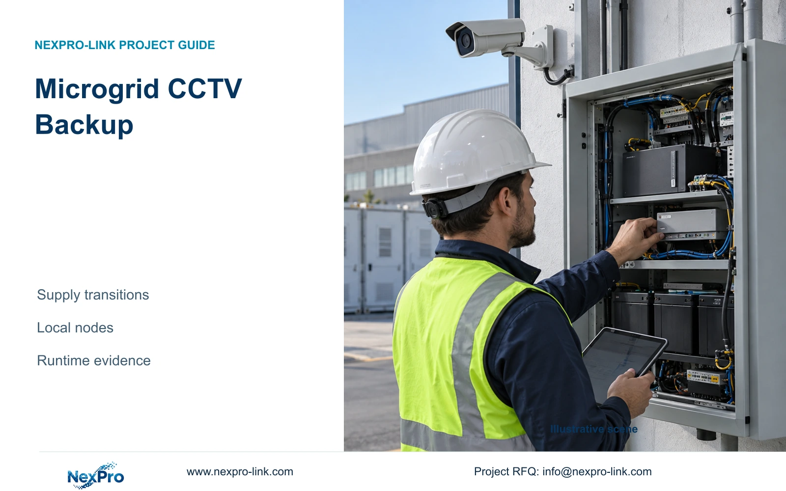
Onsite generation does not confirm continuous power at every CCTV cabinet. Define the protected security chain, evaluate microgrid transition states and request runtime evidence for the selected UPS and battery.
Section 01
Verify supply transitions at the security circuits
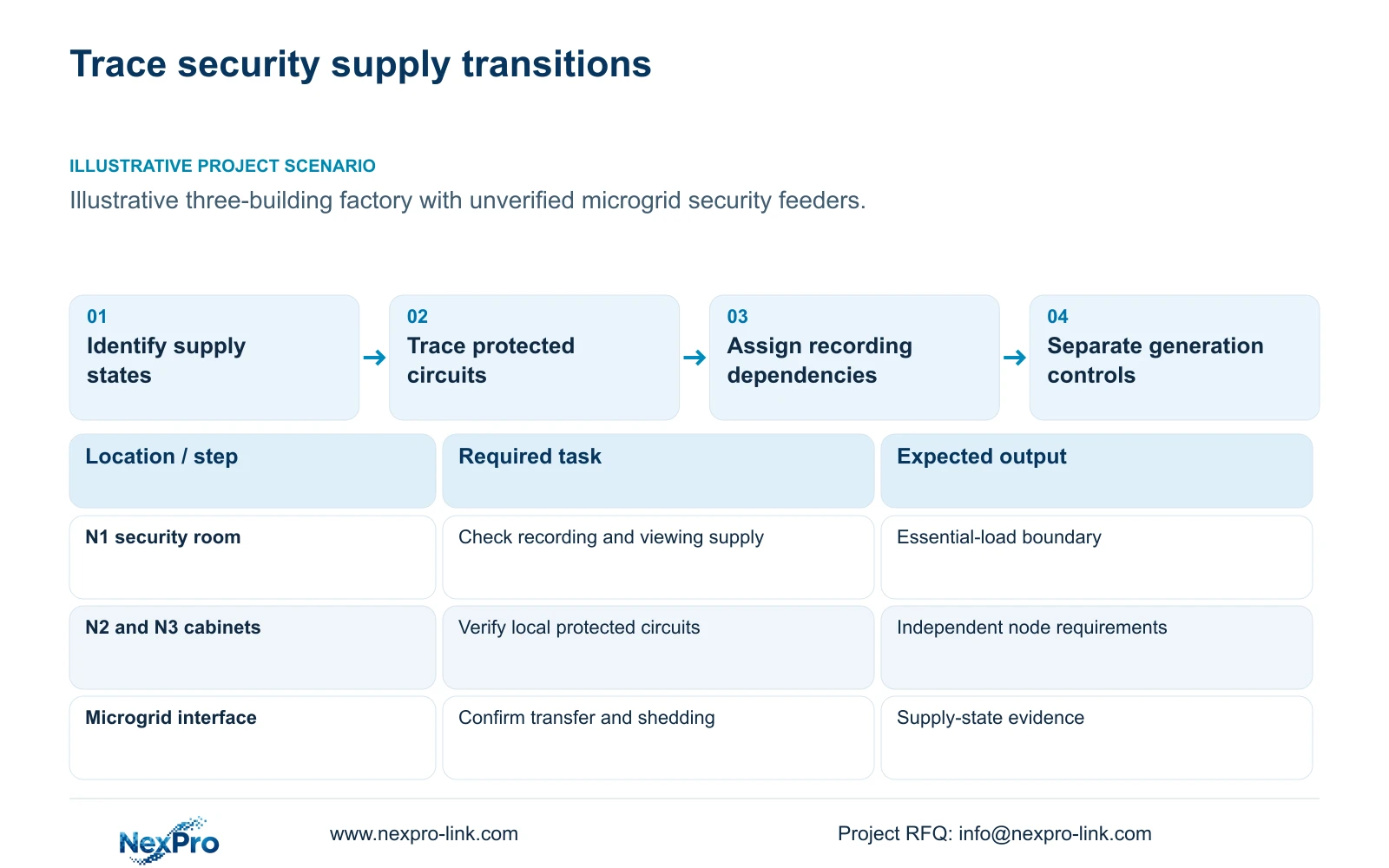
A renewable energy factory microgrid leaves a specific CCTV UPS decision: which security circuits remain powered during each supply state, and what happens between those states? Check the actual feeder and transfer behaviour before removing local backup. Onsite generation or stored energy does not establish continuity at a camera switch, recorder or remote cabinet. The required result is an agreed period of recording and operator access through the relevant interruption.
Illustrative project scenario: A factory with onsite energy storage assumes its surveillance no longer needs a separate backup discussion. Use the supplied CASE05 solar-module campus as a planning reference, with three buildings and local recording nodes. Assume the energy-system team has not yet confirmed the security feeders' behaviour during grid loss, island transition, maintenance and return to normal supply. These are unresolved design conditions, not observed failures.
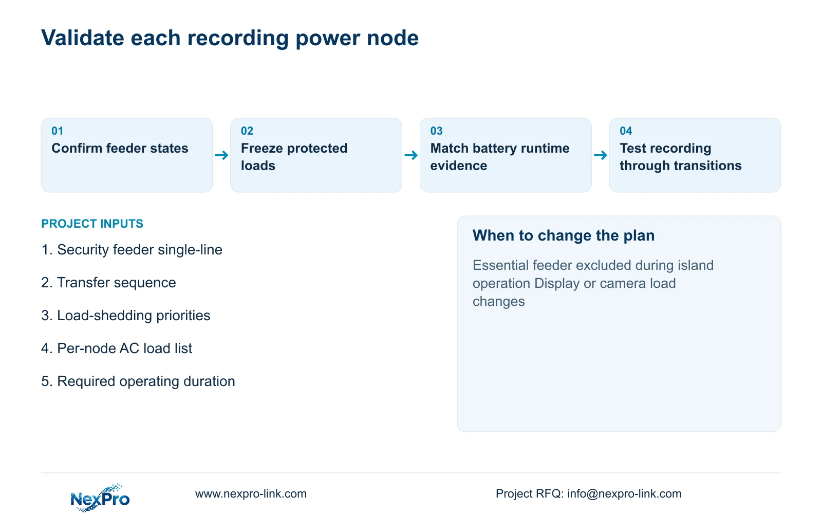
Ask that team for the electrical single-line diagram, the security circuits included in each operating state, the transfer sequence and any load-shedding priority. Record whether each condition interrupts recording, viewing or both. Include a state in which onsite storage is unavailable. The owner can then approve a continuity objective that reflects actual dependencies rather than the total battery capacity advertised for the wider site.
Section 02
Protect the devices needed to complete the recording path
Trace the security chain from camera power to local storage. For a PoE camera, the protected boundary includes the access switch supplying it, the recorder and any link equipment required for that recording arrangement. A powered recorder cannot receive useful video from an unpowered camera group. If local recording continues without the campus backbone, distinguish that resilience from the separate requirement for central viewing and remote export.
CASE05 illustrates three independent 32-camera nodes rather than one central power assumption. Its recording-first AC loads are 682.7407W at N1 and 617.7407W at both N2 and N3, using declared teaching inputs. Their 1,918.2222W total is a budgeting sum; it does not mean one central UPS protects three remote mains circuits. Associate every item with the UPS output that can physically supply it.
Build the load list from actual maximum or suitably measured demand, including recorder disks and switch conversion losses. When the complete switch AC input already includes PoE loads, do not add camera watts again. Keep operator displays as a separate decision. CASE05's optional four-panel LCD wall and decoder add an assumed 580W at N1, increasing that node to 1,262.7407W while leaving the other nodes unchanged.
Section 03
Keep CCTV continuity separate from generation control
Assign microgrid protection, energy management, battery thermal monitoring and production control to their respective specialists. The security package can preserve gate, store and transfer recordings without taking control of generation equipment. Do not place the CCTV network on an operational control network merely because the energy installation offers a convenient connection. NIST SP 800-82 Rev.3 provides a relevant OT-security reference for evaluating operational constraints and separation.
Write a responsibility schedule around the interfaces. The energy-system team confirms source and transition behaviour; the electrical contractor confirms the protected circuits and installation; the security integrator verifies recording and retrieval. NexPro-Link's equipment scope can cover the agreed CCTV and associated backup package. Each party should know which alarms it receives and which restoration decisions it is authorised to make.
Test the service outcome during an agreed, controlled transition. Check local recording continuity, camera reconnection, time references and retrieval after restoration. A microgrid status indication alone cannot demonstrate that footage remains available. If operator visibility is essential during the transition, include its network and display dependencies in the test. Keep specialist safety functions outside this security acceptance exercise and verify applicable local installation requirements separately.
Section 04
Compare backup duration before choosing the battery configuration
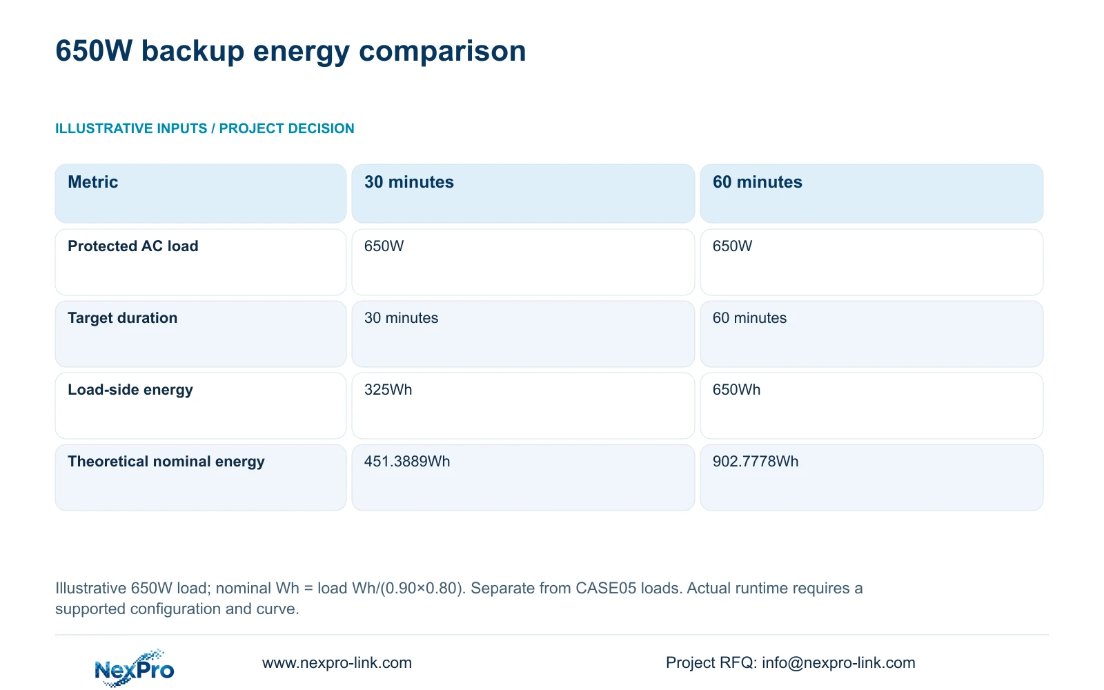
Use a separate illustrative 650W protected AC load to compare 30 and 60 minutes. This teaching module is not the CASE05 node load and must not be added to it. The formulas are load_Wh = P_W × minutes / 60 and nominal_battery_Wh = load_Wh / (0.90 × 0.80). The assumed 0.90 battery-to-load conversion factor and 0.80 usable stored-energy fraction are planning factors, not measured product efficiencies.
For 30 minutes, 650 × 30 / 60 gives 325Wh delivered to the loads, and 325 / 0.72 gives 451.3889Wh theoretical nominal energy. For 60 minutes, the corresponding requirements are 650Wh and 902.7778Wh. The decisive difference is twice the energy for the same load. Increasing the duration does not itself require twice the UPS power rating, although the supported battery configuration may change.
Select power capacity independently. With an illustrative load power factor of 0.9 and an 80% rating-utilisation target, rated_W ≥ 650 / 0.80 = 812.5W and rated_VA ≥ 650 / (0.9 × 0.80) = 902.7778VA. The quoted SP1KR(S) rating of 1kVA/900W makes it a capacity candidate under those assumptions. Its runtime still requires the exact supported battery and curve, including temperature, ageing, discharge rate, BMS limits, initial charge, self-consumption and recharge conditions.
| Metric | Option A: 30 minutes | Option B: 60 minutes |
|---|---|---|
| Protected AC load | 650W | 650W |
| Target duration | 30 minutes | 60 minutes |
| Load-side energy | 325Wh | 650Wh |
| Theoretical nominal battery energy | 451.3889Wh | 902.7778Wh |
Section 05
Match the local backup objective to the verified supply gap
Retain local recording-first protection until the security feeders' transition behaviour is established. Choose a 30-minute objective only when the owner accepts it for the documented interruption and recovery sequence. Use the 60-minute comparison where the agreed operating procedure needs that duration. Neither number is a universal factory requirement. Longer uncertainty about source restoration may require a different continuity strategy rather than a larger battery selected without evidence.
At the CASE05 reference loads, SP1KR(S) is the stated capacity candidate for each recording-first node. Adding the optional wall changes N1's candidate to SP2KR(S), whose quoted rating is 2kVA/1800W. These model ratings are separate from assumed demand and prove no operating minutes. Do not carry a selected webpage variant's 960Wh field across models. Obtain the configuration and runtime evidence for each proposed node.
A verified upstream supply may change the local backup scope, but compare complete operating states before retaining or removing equipment. Include maintenance access, recharge after an outage and the consequences of a remote cabinet losing power independently. Ask bidders to price the same protected loads, supported duration and electrical interfaces. Any claimed saving should come from matching quotations, with optional display protection and local installation work shown separately.
Section 06
Release a node schedule with measurable continuity checks
Prepare one schedule per security power node. Show the source circuit, protected outlets, equipment demand, power-factor basis, target duration, UPS rating and exact battery configuration. Include required input/output voltage and the approved connection arrangement. Preserve the actual recording stream and disk specification because equipment substitutions can change load as well as storage. Do not infer decoding or RAID capability from the recorder's channel count.
Set acceptance checks around the required service: recordings continue through the selected transition, essential clients retain their access path, and footage can be retrieved after restoration. Record the tested load, battery condition and configuration so the result can be compared with the supplier's curve. Define how low-energy conditions are handled and who authorises recovery. Repeat the affected checks when circuits, cameras or viewing loads change.
NexPro-Link can discuss the coordinated equipment list, UPS capacity candidates and technical quotation through its factory project and BOQ support scope. The energy-system team supplies transition evidence, and the local electrical team confirms installation. The resulting procurement package should expose the remaining decisions before the purchase order: an unresolved supply state or missing battery configuration is an input to resolve, not a runtime guarantee.
Section 07
Buyer questions
Can a larger microgrid battery replace the local UPS automatically? No. First establish that the relevant security circuits are supplied through every required state and that transitions suit the connected equipment. Stored energy elsewhere on the site does not resolve a feeder interruption or an excluded remote cabinet.
Should runtime be specified with the display wall switched off? Specify the operating state explicitly. If essential views must stay visible, include their processing, display and network loads. If displays are intentionally disconnected during an outage, define that action and quote runtime for the resulting protected load.
What evidence should accompany a battery proposal? Request the exact UPS and supported battery configuration, a runtime curve at the proposed load, the curve's operating conditions and recharge information. A nominal Wh figure alone is insufficient to accept the requested duration.
Section 08
Check your CCTV continuity boundary
Send the security feeder single-line diagram, microgrid transition and load-shedding sequence, per-node AC load list and required recording/viewing duration to info@nexpro-link.com for a coordinated CCTV backup-power quotation discussion.
Engineering references
These sources support the general planning principles. Always use the selected product's current datasheet and applicable project standards for final design.