
01
Cabling and ELV contractors
Matched termination products from the approved outlet schedule.
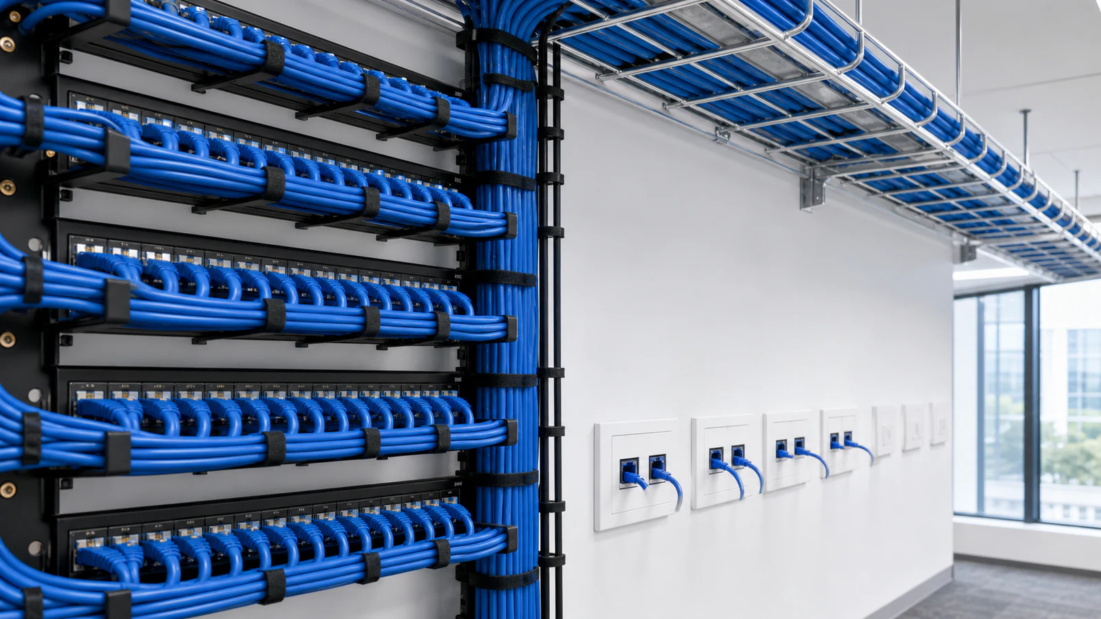
Turn the outlet and rack schedule into matched patch panels, faceplates, keystone modules, terminations, labels and project records.
System definition
The design starts with the outlet and service schedule: data or voice use, cable category, shielding, port quantity and rack destination. Patch panels, keystone modules and faceplates are matched from that schedule.
NexPro-Link supplies and coordinates current connectivity products and quotation records. Cable routing, final performance design, installation and field testing remain with the project's qualified cabling contractor.

Who this solution is for
For structured-cabling contractors, ELV integrators, consultants and procurement teams preparing rack and outlet schedules for commercial network and low-voltage projects.
01
Matched termination products from the approved outlet schedule.
02
Rack connectivity aligned to switches, devices and cabinets.
03
A controlled port, labeling and product quotation basis.
Problems this system solves
These are the decisions a BOQ or source list has to answer before individual products become a coherent system.
Data or voice use, cable category and shielding must be defined from the project schedule rather than assumed from a generic panel.
Outlets, patch-panel ports, switch ports, spare capacity and rack units have to reference the same approved count.
Modules, faceplates, labeling, packing and test-record requirements are part of the deliverable, not late accessories.
System architecture
Follow the operating path from the first project input through control, operation and protected infrastructure.
The user or ELV device connects at a labeled faceplate.
The project cable route connects the outlet to the telecom room.
The link terminates at the matched patch panel.
Patch leads connect the panel to the active network or ELV equipment.
The final port map and tests verify the installed connectivity.
Functional modules
Each module has a distinct job and a defined set of inputs. The final quotation keeps those roles visible.
Faceplates and modules matched to the outlet type and service.
Patch panels matched to category, shielding and port density.
Keystone and termination method coordinated with the selected panel and field cable.
Labels and test requirements make the installed system traceable.
Visual project reference
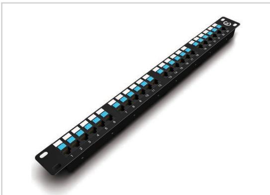
Patch-panel and voice-termination references connect abstract cable counts to rack space, port density and labeling work.
 Product reference
Port-density reference for matching horizontal links, rack allocation and the labeling schedule.
View details Equipment detail
A higher-density termination reference for projects with concentrated rack-side copper links.
View details Product reference
Voice termination hardware is reviewed separately from data cabling so port and labeling assumptions stay visible.
View detailsApplication scenes are visual references. Final models, quantities and interfaces follow the approved project information.
Product database source
These are selected current products from the NexPro-Link product database. They illustrate system roles; the final model mix follows the approved project inputs and compatibility review.
SP5524
A current Cat5e 24-port data panel reference for compact rack schedules where its category and port density match the project.
SP5648
A current Cat6 48-port data panel reference for higher-density rack distribution after category and shielding are confirmed.

SP8602
A current two-port 86-type faceplate for work-area outlets that require two modular network or voice positions.

DT968MX
A current Cat6 tool-free module for compatible faceplate and panel terminations within the approved cable system.
Product category mapping
These category links provide the full product and specification context. The solution page stays focused on how the equipment works together.
Engineering and selection inputs
A useful review separates buyer inputs from compatibility checks so open assumptions are visible before quotation.
Starting configurations
These are scope frameworks, not fixed kits. Quantities and models remain subject to the project drawing, BOQ and compatibility review.
CONFIG 01
Small office, retail or CCTV cabinet with a limited outlet schedule.
Confirm before quotation: Confirm outlet count, category, panel space, switch ports and spare allowance.
CONFIG 02
Office, hotel, school or retail floors with multiple work-area outlets.
Confirm before quotation: Confirm floor-by-floor outlet map, telecom rooms, category, shielding and test standard.
CONFIG 03
Projects carrying separate network and voice services in one equipment room.
Confirm before quotation: Confirm data and voice counts, termination method, active-equipment boundary and cross-connect workflow.
Technical submittal
Document availability and revision are confirmed against the models included in the final quotation. The download center provides general selection forms and project checklists.
Open the technical download centerOEM / ODM scope
Selected connectivity products can be reviewed for project labeling, packing, color and configuration requirements.
Final channel performance depends on the complete installed cabling system, workmanship and field testing; product supply alone does not certify the installed link.
Review OEM and ODM supportRelated project applications
Industry pages keep the Project Supply intent separate while showing how this system is quoted in a real application.
Related technical guides
FAQ
Answers reflect NexPro-Link's equipment-supply and compatibility-review role; project-specific values remain subject to the final BOQ and approved models.
Send the outlet schedule, data or voice service, cable category, shielding, panel port count, faceplate type, module requirement, spare allowance, labeling and test-record requirements.
Yes. We map current panel, keystone and faceplate products to the approved outlet and rack schedule, with category and port-count assumptions stated.
The selected cable, panel, module, patching and shielding design must form one compatible channel. NexPro-Link reviews the supplied products while the cabling contractor validates the complete installed link.
No. NexPro-Link supplies coordinated products and data. Installation workmanship, field testing, certification and local compliance remain with the qualified project cabling team.
BOQ / RFQ review
Share the BOQ, BOM, drawing or equipment schedule. NexPro-Link will review system roles, current models, compatibility assumptions and the coordinated supply scope.