01
Security integrators
A source-to-screen configuration and protocol review.
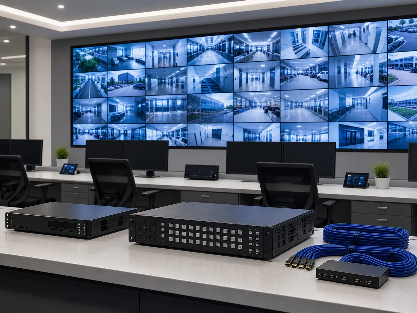
Map surveillance and workstation sources through decoding, display, operator control, racks and protected power for a coordinated security command center.
System definition
The design starts with the source list: camera streams, NVR outputs and operator workstations. Their formats and simultaneous viewing requirements determine decoder capacity, physical outputs, wall layout and management functions.
Display, decode, control, rack and power should be reviewed as one room architecture. NexPro-Link coordinates the equipment package while room construction, installation and local commissioning remain with the project team.

Who this solution is for
For integrators, consultants and contractors turning a tender, room drawing and source list into a reviewable display, decode, control, rack and power scope.
01
A source-to-screen configuration and protocol review.
02
Clear assumptions for wall layout, capacity and infrastructure.
03
Coordinated display, rack, cabling and protected-power inputs.
Problems this system solves
These are the decisions a BOQ or source list has to answer before individual products become a coherent system.
Every IP stream, recorder output and workstation source has to be mapped to decoder capacity, window layouts and physical screen outputs.
Panels, decoder modules, matrix management, PTZ control and KVM depend on one operator workflow and cannot be selected in isolation.
Viewing distance, maintenance clearance, rack space, PDU outlets and UPS runtime determine whether the designed wall is usable and supportable.
System architecture
Follow the operating path from the first project input through control, operation and protected infrastructure.
IP streams and physical outputs enter from surveillance and operator systems.
The decoder and management layer maps sources to simultaneous windows.
Panels present the approved rows-by-columns layout.
PTZ keyboards and KVM provide controlled access to sources and systems.
Racks, distribution and UPS protect the command-center equipment.
Functional modules
Each module has a distinct job and a defined set of inputs. The final quotation keeps those roles visible.
LCD panels and mounting matched to rows, columns, viewing distance and service access.
Network decoding and layout control matched to source load and screen outputs.
PTZ and KVM access organized around the real operator workflow.
Racks, PDU and UPS provide organized, maintainable power and equipment access.
Visual project reference
A command-center scope becomes clearer when the display environment, decoder hardware and controller interfaces can be reviewed together.
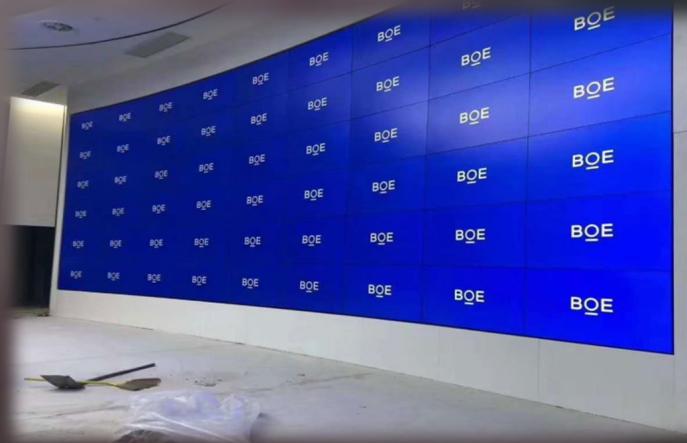 Application reference
Supplier installation reference for viewing scale and operator context; it is not presented as a named NexPro customer project.
View details Product reference
A current decoder reference for matching input sources, decoded outputs and display destinations.
View details Equipment detail
Rear-panel detail helps confirm signal types, control connections and the cable schedule before quotation.
View detailsApplication scenes are visual references. Final models, quantities and interfaces follow the approved project information.
Product database source
These are selected current products from the NexPro-Link product database. They illustrate system roles; the final model mix follows the approved project inputs and compatibility review.

NX-VP-5535
A current display-layer model for tiled Full HD control-room walls; quantity and mounting follow the approved wall layout.
NX-VD-4K16
A current modular decoder platform for mapping reviewed network sources and multi-window layouts to the display wall.

NX-PC-5S3
A current operator-control model for PTZ and device operation after protocol and managed-device review.
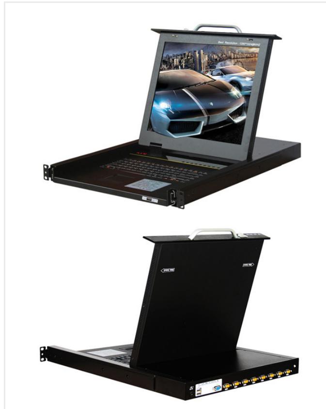
SP1708-B
A current local KVM reference for rack equipment access where eight VGA-managed devices fit the confirmed operator workflow.
Product category mapping
These category links provide the full product and specification context. The solution page stays focused on how the equipment works together.
Project-configured LCD display, 4K network decoding, matrix management and PTZ control for professional monitoring and command rooms.
Explore Video Wall products 027 consolidated KVM model and product-group pages for local, IP and CAT5 server administration.
Explore Rack KVM products 0312 consolidated cabinet and containment pages covering KP-C shielding, K1/K2 network cabinets, K5 server cabinets and cold-aisle projects.
Explore Rack Cabinets products 0423 model, product-group and intelligent-PDU series pages organized by outlet, protection, monitoring and installation requirements.
Explore Rack PDU products 05Project-configured UPS, DC backup, portable power, hybrid inverter and LiFePO4 energy storage systems for security, network, telecom, residential backup and industrial applications.
Explore UPS Power productsEngineering and selection inputs
A useful review separates buyer inputs from compatibility checks so open assumptions are visible before quotation.
Starting configurations
These are scope frameworks, not fixed kits. Quantities and models remain subject to the project drawing, BOQ and compatibility review.
CONFIG 01
Small control rooms with a limited source set and 2 × 2 display reference.
Confirm before quotation: Confirm exact sources, simultaneous windows, maintenance access and mounting before quotation.
CONFIG 02
Medium monitoring centers using 2 × 3 or 3 × 3 display references.
Confirm before quotation: Confirm wall geometry, source load, operator count, scenes and redundancy requirements.
CONFIG 03
Large projects combining surveillance, workstations and third-party sources.
Confirm before quotation: A source-to-screen matrix and room drawing are required before capacity is fixed.
Technical submittal
Document availability and revision are confirmed against the models included in the final quotation. The download center provides general selection forms and project checklists.
Open the technical download centerOEM / ODM scope
Selected display and control products can be reviewed for project branding, interface labels, packing and document presentation.
Room design, mounting engineering, software integration and final commissioning are project-specific and require approval by the appointed integrator or contractor.
Review OEM and ODM supportRelated project applications
Industry pages keep the Project Supply intent separate while showing how this system is quoted in a real application.
Related technical guides
FAQ
Answers reflect NexPro-Link's equipment-supply and compatibility-review role; project-specific values remain subject to the final BOQ and approved models.
Send the room drawing, source list, rows by columns, panel size, viewing distance, simultaneous layouts, PTZ and KVM workflow, rack space, power load and UPS runtime.
Yes. We coordinate display, decode, operator control, rack, PDU and UPS as one equipment architecture, with open assumptions identified before quotation.
The review maps source codecs, resolutions, channel counts and simultaneous windows to decoder capacity and physical display inputs, then checks control and management interfaces.
NexPro-Link is an equipment and project-supply partner. Site installation, integration and commissioning are performed by the appointed local project team.
BOQ / RFQ review
Share the BOQ, BOM, drawing or equipment schedule. NexPro-Link will review system roles, current models, compatibility assumptions and the coordinated supply scope.