 Display Layer
NX-VP-5535
55-inch LCD Video Wall Panel for Control Room Display
Forms the physical multi-screen wall. Quantity, geometry, mounting and service access are configured from the room drawing.
55 inches3.5 mm1920 × 1080400 nit typical
Integrated LCD panels, 4K network decoding, matrix management and PTZ control — matched to your source count, wall layout, operator workflow and installation conditions.

LCD panels and project layouts sized for the room and viewing requirement.
Network decoders matched to source count, codec, resolution and output load.
Source mapping, windows, presets and operator permissions for the approved release.
PTZ keyboards and operator workflow integrated where the project requires them.
Select a layer to see what must be confirmed before the model, module count and project BOM are released.
Decode IP streams, map sources, recall scenes and output the approved multi-window layout to the display wall.
Engineering rule: configuration starts from the complete source-to-screen workflow, not from a single panel or decoder model.
Evaluate each model as part of the complete system architecture, not as an isolated catalog item.
Display LayerForms the physical multi-screen wall. Quantity, geometry, mounting and service access are configured from the room drawing.
 Decode & Manage Layer
Bridges IP camera and NVR sources to the wall, then resolves layouts and simultaneous output requirements.
 Control Operation Layer
Provides direct operator control for PTZ cameras and compatible video resources at the monitoring desk.
 Control Operation Layer
Provides direct operator control for PTZ cameras and compatible video resources at the monitoring desk.
Review actual supplier software screens for source mapping, layouts, window control, scenes and user workflow. Exact functions are confirmed from the configured release.
 Interface 01 / 13
Web-based access and authenticated operator entry.
Software version, browser support, protocol behavior and licensed modules must be confirmed in the project submittal.
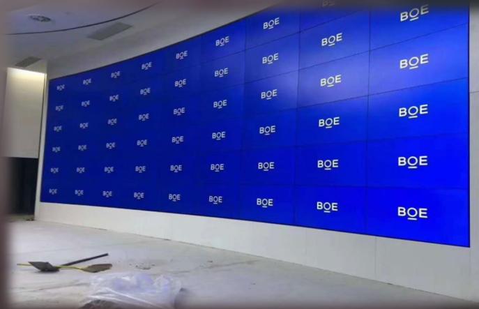
Real project photos show why layout, room geometry, service access and operator viewing distance must be evaluated before selecting the system BOM.
4 × 7 / 28 panelsUse the room drawing and source list to convert the visual goal into panel, decoder, mounting and power requirements.
 3 × 9 / 27 panels
Use the room drawing and source list to convert the visual goal into panel, decoder, mounting and power requirements.
3 × 9 / 27 panelsUse the room drawing and source list to convert the visual goal into panel, decoder, mounting and power requirements.
 3 × 3 / 9 panels
Use the room drawing and source list to convert the visual goal into panel, decoder, mounting and power requirements.
 1 × 28 / 28 panels
Use the room drawing and source list to convert the visual goal into panel, decoder, mounting and power requirements.
 Project layout
Use the room drawing and source list to convert the visual goal into panel, decoder, mounting and power requirements.
 Project layout
Use the room drawing and source list to convert the visual goal into panel, decoder, mounting and power requirements.
 Project layout
Use the room drawing and source list to convert the visual goal into panel, decoder, mounting and power requirements.
A video wall is not a fixed package. The approved combination of panels, decoder capacity, management functions, controls, mounting and UPS depends on the room and signal workflow.
Send the information you already have. Unconfirmed items will be returned as engineering questions instead of guessed specifications.
Use this checklist before requesting a technical configuration or tender quotation.
These documented installation stages help integrators identify the drawings, structure, access and commissioning scope needed before shipment.

Verify delivered units, accessories and visible condition before assembly.

Confirm the approved base, load path and room dimensions.

Build the support structure to the approved rows × columns drawing.

Provide the front- or rear-maintenance access required by the project.

Install panels carefully and protect the LCD edges during alignment.

Separate, label and verify the cable plan before commissioning.

Verify addressing, wall layout, source mapping and visual consistency.
Answers describe the selection process. Final functions, interfaces and quantities remain subject to the approved project configuration.
Ask the engineering teamThe project scope can combine reviewed LCD panels, network decoding, matrix management, PTZ controllers, mounting references, network accessories and UPS matching. Final models and quantities depend on the project inputs.
Capacity is reviewed from source type, channel count, codec, stream resolution, simultaneous windows, target wall outputs and required redundancy. A model number alone is not enough for final sizing.
The reviewed decoder supports ONVIF, GB28181, RTSP, RTP and SDK integration. Compatibility still needs confirmation by platform, device model, firmware and required workflow.
Provide display technology and layout, signal list, operator functions, existing platform information, installation method, maintenance space, UPS target and delivery destination. Uncertain items can be marked for engineering review.
Send display layout, source list, control functions, site conditions and destination. The response can then define the reviewed models, quantities and confirmation points.
Download the product portfolio and find specifications for your selected model.
Product range, model specifications and application references.
Document language: English
NX-VP-5535 · NX-VD-4K16 · NX-PC-5S3 · NX-PC-5HD
Model and category questions for system integrators, distributors and contractors preparing an RFQ.
Prepare the screen technology, panel size, rows by columns, room dimensions, viewing distance, source list, layout requirements, mounting conditions, maintenance access, power load and delivery destination.
Yes. We review the display layer, network decoder, matrix management software, PTZ controller, cables, mounting structure and UPS backup as one control-room system scope.
Start with viewing distance, bezel expectation, brightness, control-room layout, maintenance access and budget. NexPro-Link can help compare practical options after the site and source list are clear.
Yes, but the exact design depends on IP camera channels, NVR outputs, workstation sources, decoder capacity, window layout and operator workflow. Send the source list for engineering confirmation.
Provide the display layout, panel role, source count, input and output formats, window layout, control method, room dimensions and service-access requirement.
Match source codec and resolution, simultaneous decode load, physical outputs, display quantity and management functions to the reviewed decoder, matrix and panel models.
Yes. Send the equipment list, drawing or tender reference. The review can identify matching catalog models, related accessories and the model-level documents that are available for the selected scope.
List the required protocol, connector, voltage, software or system interface. Compatibility is checked against the selected model information and is recorded as a confirmation point before order approval.
Provide the target model, quantity, destination, logo position, label, manual language and packaging requirement. Available OEM scope and minimum quantity are confirmed per model in the quotation.
Commercial terms are confirmed for the exact model, quantity, destination and order stage. Use the issued quotation and order documents rather than a generic website statement.
Yes. Send the complete list and destination. Packing compatibility, carton grouping, document scope and the practical shipment method are reviewed before the order is confirmed.
Send the target market, tender clause and exact model list. Only documents that match the selected model and stated scope should be used for approval.
Need a model-specific answer? Send the product list for review.