Closing switches into a ring does not prove CCTV continuity. Define supported recovery, distinguish link loss from access-group failure, and verify the footage produced during each accepted test.
Section 01
Require supported loop control before closing the ring
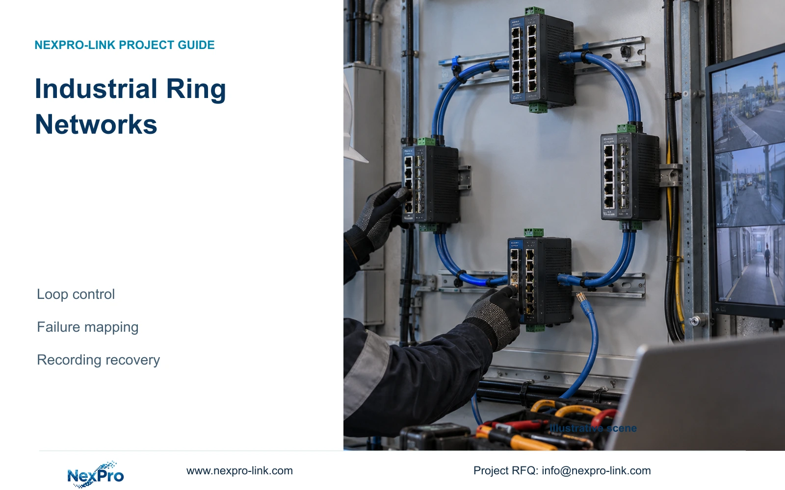
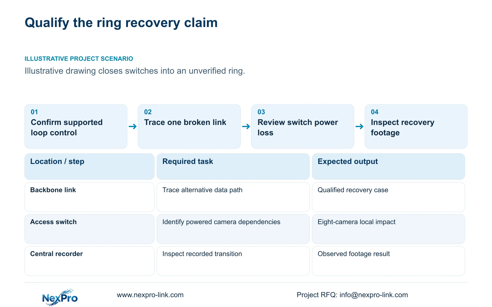
Specify an industrial CCTV ring only with a supported and configured loop-control and recovery method, followed by an accepted test. An unmanaged physical loop can disrupt the network. Until the exact switch and firmware arrangement is qualified, describe the drawing as a proposed ring rather than established redundancy.
Illustrative project scenario: The drawing closes several switches into a ring and labels it resilient. Use the CASE01 planning scope of 32 ordinary security cameras and four eight-camera access groups to review the claim. The supplied reference establishes no ring protocol, switch model or measured recovery time, so those remain design inputs.
Ask the bidder to identify the supported method, participating devices, firmware and intended normal forwarding arrangement. Require a configuration responsibility and an acceptance objective tied to recording. A model name containing industrial, or a line completing a circle on the drawing, cannot substitute for these records.
Section 02
Trace a broken link separately from a failed switch
For each backbone link, draw the intended remaining path after that link is disconnected. Identify which camera groups can still reach the recorder and which interfaces now carry additional traffic. A recovery path must be supported and have capacity for the changed forwarding case.
Then review access-switch failure separately. If a switch supplying eight cameras loses power, another backbone route does not automatically restore those camera power and port connections. A ring can address a qualified path-loss scenario while leaving endpoint-supplying equipment as a local dependency.
CASE01 also contains one common recorder and one electrical node. A common recorder or upstream power failure can affect the complete system regardless of four access groups. The NexPro-NVR4449-4K source lists dual Gigabit LAN, but it does not establish automatic recorder failover. Do not let network recovery language imply that unsupported capability.
Section 03
Measure the recording result during recovery
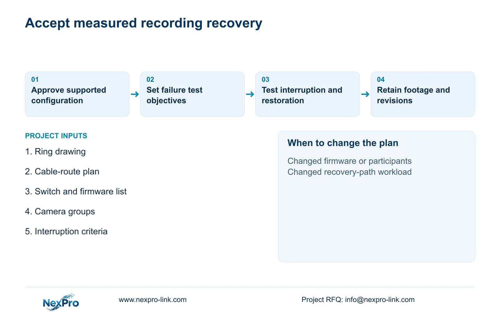
Agree the test objective before installation. Specify the cameras observed, operating streams, accepted interruption criterion and evidence to retain. The owner should define the usable recording requirement; the integrator identifies the supported test method; the network administrator approves any action affecting retained infrastructure.
Run planned single-link interruption and restoration checks under the intended recording workload. Record interruption and recovery observations rather than inserting an unsupported time target. Inspect stored footage and export representative intervals, because a live picture returning does not establish what the recorder retained during the transition.
Include the restoration state and relevant management access in the record. A design that works only after manual intervention needs that intervention documented. NIST SP 800-82 Rev.3 supplies the OT-security context for protecting operational constraints, so factory tests must be planned around production responsibilities rather than performed as casual cable-pulling demonstrations.
Section 04
Use access-group size to quantify local impact
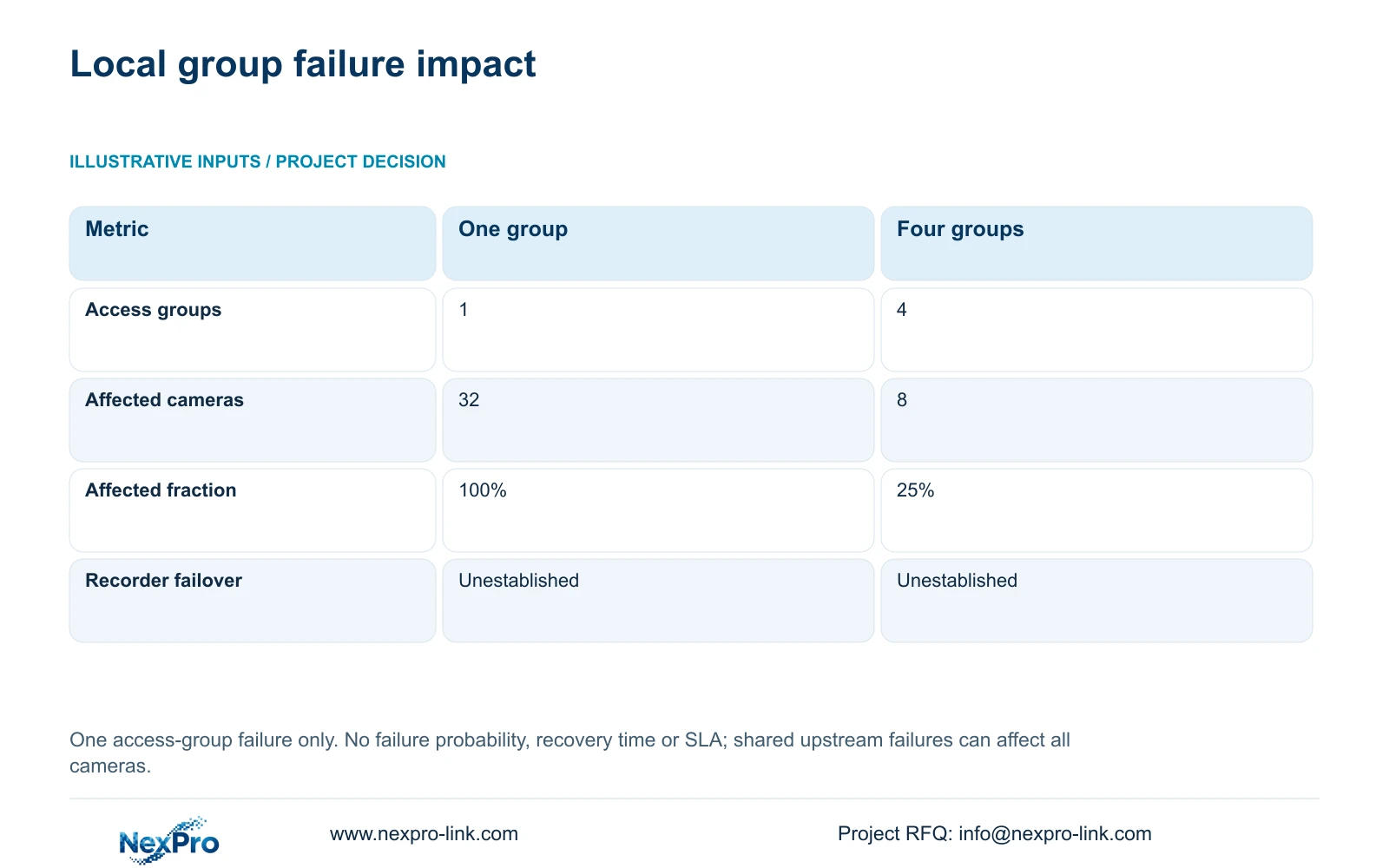
The supplied deterministic comparison analyses one access-group failure, not ring recovery. Option A places all 32 cameras in one common group. Option B uses four locally isolated groups of eight. Calculate affected_endpoints = camera_count_in_failed_group and affected_fraction = affected_endpoints / 32.
One group failure therefore affects 32 cameras, or 100%, in Option A and eight cameras, or 25%, in Option B. The decisive difference is the number of endpoints dependent on the failed group. It supports limiting local impact, but does not establish a lower failure probability or a recovery-time improvement.
The four groups are isolated only for the stated local failure boundary. Shared upstream power, aggregation or recording can still affect them all. Keep this table beside a failure map so procurement does not mistake group partitioning for four fully independent systems or a tested ring design.
| Metric | One common group | Four groups |
|---|---|---|
| Access groups | 1 | 4 |
| Cameras per failed group | 32 | 8 |
| Affected fraction | 100% | 25% |
| Automatic recorder failover | Not established | Not established |
| Ring recovery measured | No | No |
Section 05
Choose a ring only for a defined recovery benefit
Retain a simpler approved topology when it meets the required service and no qualified ring arrangement is available. Choose a ring when the project has a meaningful link-failure objective, supported equipment and an agreed test. Keep the ring conditional until commissioning establishes the accepted result.
Compare the full additional scope: suitable switches, ports, optical components, return route, protected supplies, configuration and testing. A return cable sharing an exposed route with the outward cable may leave a common physical dependency; record the actual routing without claiming diversity from a diagram alone.
For CASE01's 4 Mbps camera assumption, normal recording totals 128 Mbps payload. Recalculate per-link traffic for the recovery path, including applicable viewing and exports. A ring that moves traffic onto an inadequately sized remaining link can preserve connectivity without meeting the usable recording task.
Section 06
Purchase the recovery configuration and its evidence
Issue the RFQ with the ring drawing, failure scenarios and acceptance objective. Require bidders to return exact supported hardware and firmware, a configuration scope and a list of unresolved dependencies. Separate supplied equipment from retained infrastructure, including who approves changes to existing network management.
NexPro-Link's BOQ and Tender Support scope can coordinate CCTV equipment matching and documented deviations against those requirements. Its factory project supply scope includes recording and related project inputs, but no supplied source establishes a particular ring-capable switch. Keep network equipment as a functional requirement until its evidence is provided.
Handover should retain configuration revisions, link identities, approved test records and the response procedure for a future failure. Label the ring and access groups consistently in packing and drawings. Requalification is needed when firmware, participating switches, physical routing or the recording workload changes the basis of the accepted recovery result.
Section 07
Buyer questions
Can four access groups protect against recorder failure? They limit the stated local access-group impact. Recorder failure remains a separate shared dependency unless an actual supported recording resilience design is selected and verified.
Can a supplier's recovery-time claim become our recording acceptance result? Use it as a supported product input where applicable, then test the selected configuration against the project's recording task. Network recovery and a stored-video gap are different observations.
Should a restored link be included in commissioning? Yes. Record both interruption and restoration behaviour under the agreed workload, including any manual action needed to return to the accepted state.
Section 08
Qualify the proposed CCTV ring
Send your ring and cable-route drawing, proposed switch/firmware list, camera group assignments and recording interruption criteria to info@nexpro-link.com for a supported equipment and deviation review.
Engineering references
These sources support the general planning principles. Always use the selected product's current datasheet and applicable project standards for final design.