Compare wall and pole options using the same replacement-access task, including permitted access windows and affected traffic. Ask the responsible installer/designer to identify supporting work and interruption constraints.
Section 01
Approve the viewpoint before choosing the support
Compare wall and pole options using the same replacement-access task, including permitted access windows and affected traffic. Ask the responsible installer/designer to identify supporting work and interruption constraints. Keep structural approval separate from image acceptance. A cheaper bracket is not a complete alternative when its service method changes the operating scope.
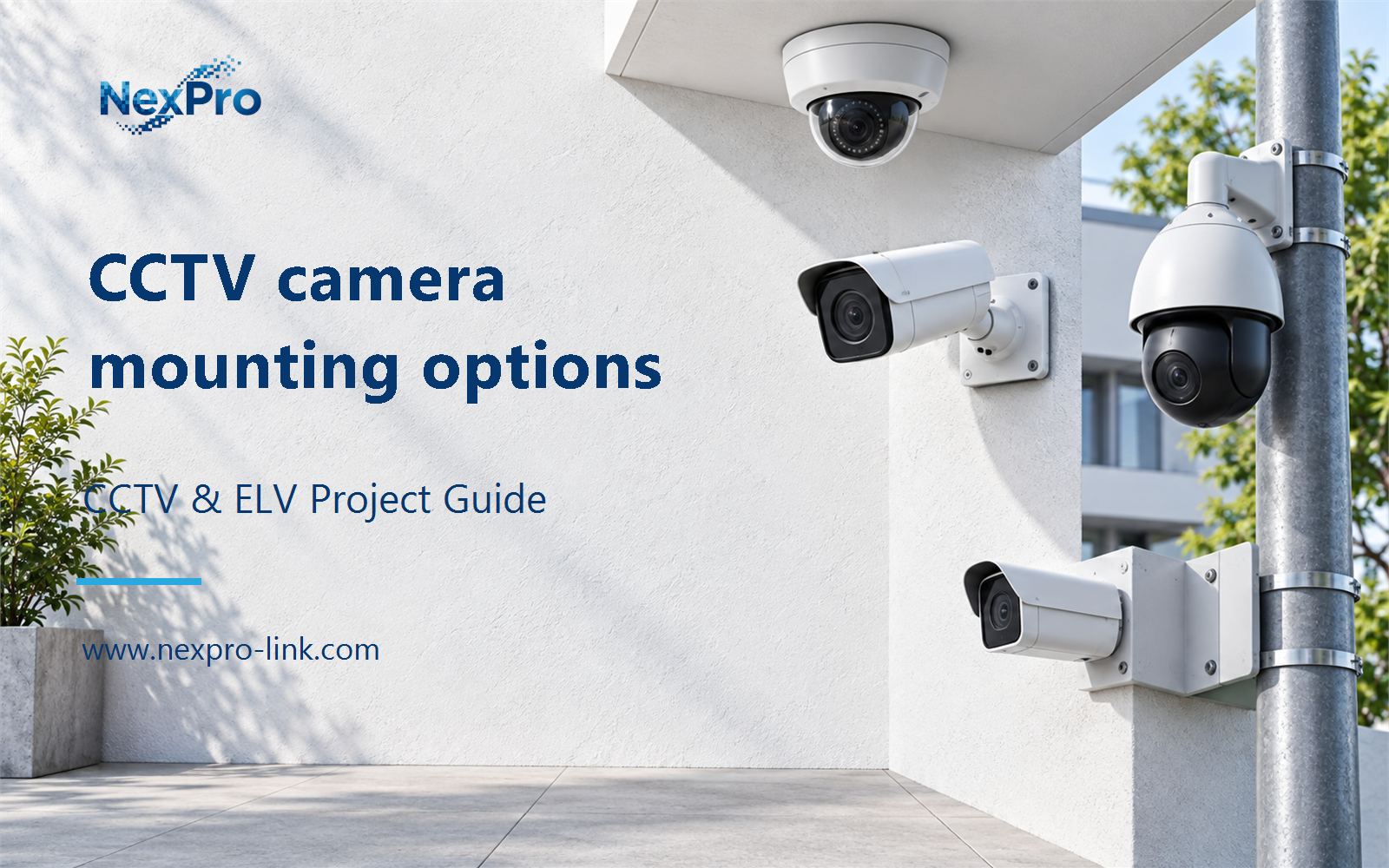
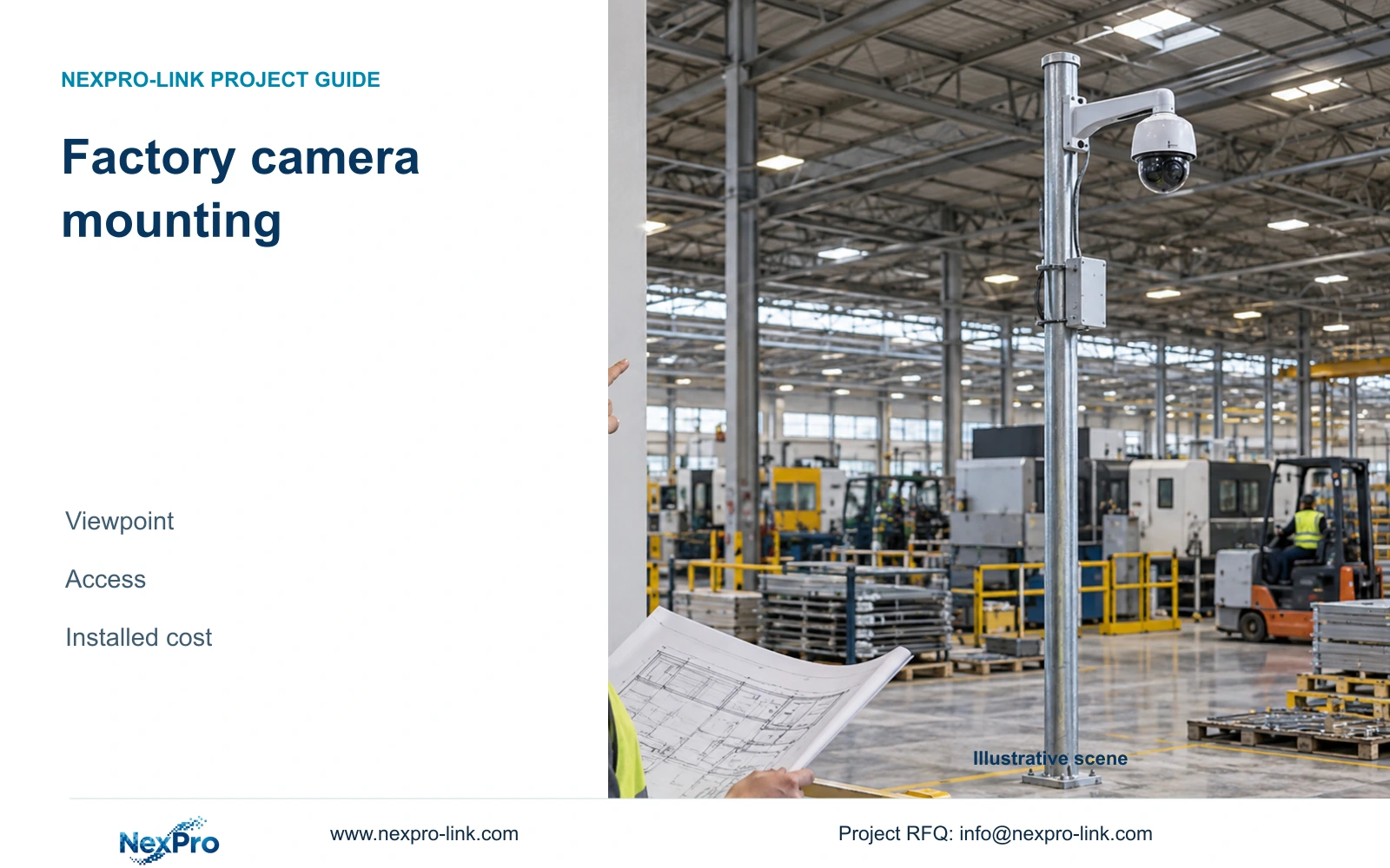
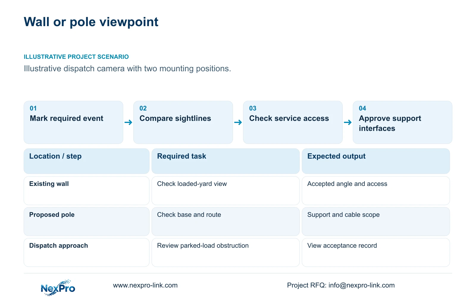
Choose factory camera poles and brackets by the view they deliver and the access they require. An existing wall is the preferred starting point when it provides the accepted observation angle, a suitable fixing location and workable maintenance access. A standalone pole becomes justified when the wall position leaves the required event obscured or places the camera too far from it. Compare both as complete installed positions before approving either support.
Illustrative project scenario: A camera in a new CNC factory can be mounted on an existing wall or a new standalone pole. Using CASE01 as the planning background, the factory has 32 ordinary security views covering access and material transfers. Assume this particular decision concerns a dispatch approach where parked loads may obstruct the wall view. The obstruction is a planning assumption to investigate, not an observed customer result.
Mark the required event area, camera height and viewing direction on the same drawing for both options. Check the scene with expected vehicles and stored materials present. Then identify how an installer reaches the camera for alignment, cleaning and replacement. Raising the camera may clear an obstruction while making the required detail harder to assess; approve the image task and service position together.
Section 02
Separate structural approval from equipment selection
Once the viewpoint is acceptable, obtain a mounting arrangement that the responsible site designer can assess. For a wall option, record the substrate, fixing area, bracket projection and any restrictions on drilling. For a pole, identify the proposed base location, underground-service constraints, attached equipment and cable entry. A camera supplier's accessory match does not resolve whether the supporting structure is suitable.
Ask the structural designer to review the actual assembly, including any enclosure or additional device attached to it. Keep the approved fixing or foundation detail with the camera location record. The quantity surveyor can then distinguish the camera bracket from structural work, excavation, reinstatement and access equipment. Where information remains missing, retain a provisional allowance or clarification rather than treating the work as included.
Electrical protection and cable entry also need an assigned local designer or installer. Show the route into the support, connection enclosure and relevant protection interfaces. A pole that moves the camera into an exposed yard may change these requirements even when the camera model stays unchanged. Confirm applicable local installation requirements before finalizing the detail; do not transfer a wall installation allowance unchanged to the pole option.
Section 03
Price the continuous route and maintenance access
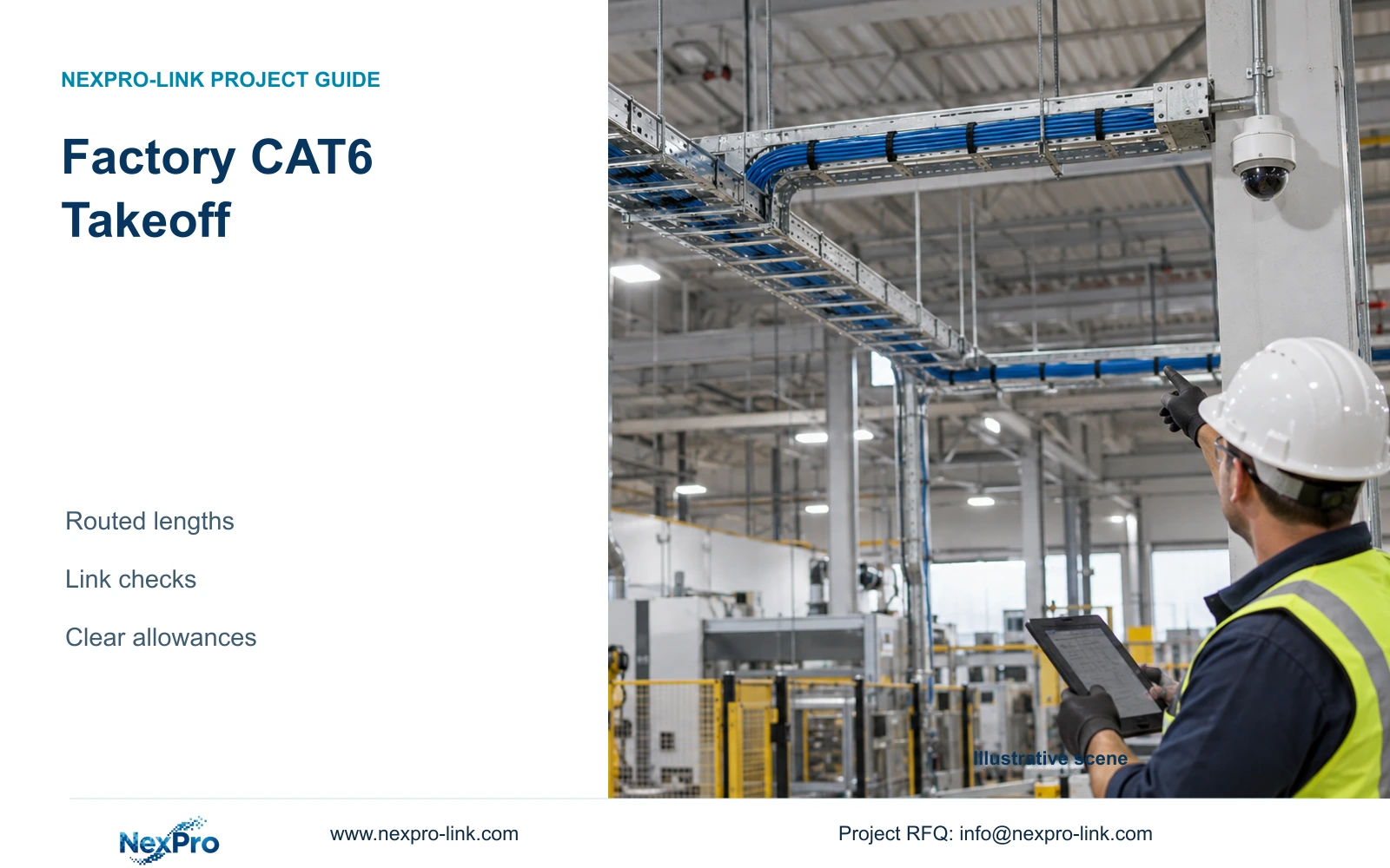
Measure the cable route to each candidate position through the intended tray, riser, duct and support. List horizontal travel, vertical travel and service or termination allowance separately. This lets the engineer revise the height without obscuring the reason for a length change. Keep patch cords separate from the permanent-link takeoff and specify how the camera end will be terminated.
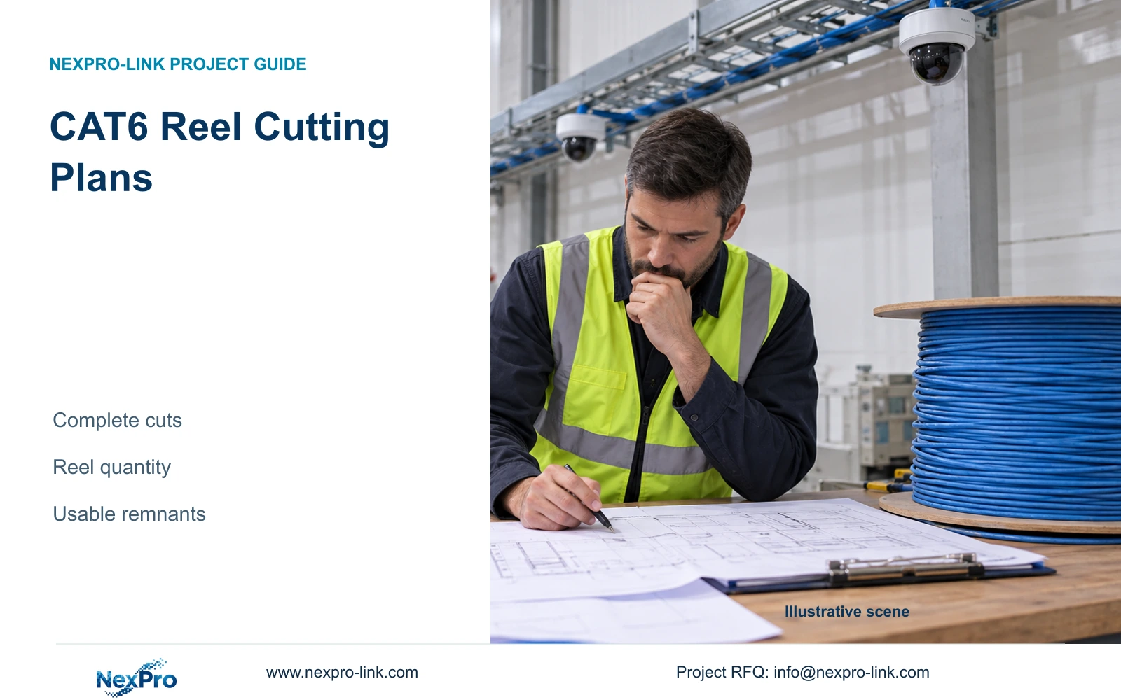
CASE01 illustrates the purchasing consequence: its assumed base routes are 35 to 70 m, with 6 m added per link for service and termination, producing continuous cuts of 41 to 76 m. Across 32 links, the total is 1,872 m. The lower bound is ceil(1,872/305) = 7 reels, and the supplied cutting allocation fits seven 305 m reels. This is a feasible plan, not a claim of global optimization.
A changed pole position requires a revised cut allocation; spare metres scattered across reels do not form one continuous replacement link. Check the resulting installed link against its specified test arrangement. Fluke Networks guidance distinguishes the typical 90 m permanent link from the 100 m complete channel. NexPro-Link's SP5648 patch panel and DT968MX module are termination references, not bulk cable specifications. Include lifting access and any required production-access window as separate installation items.
Section 04
Normalize both quotations before comparing totals
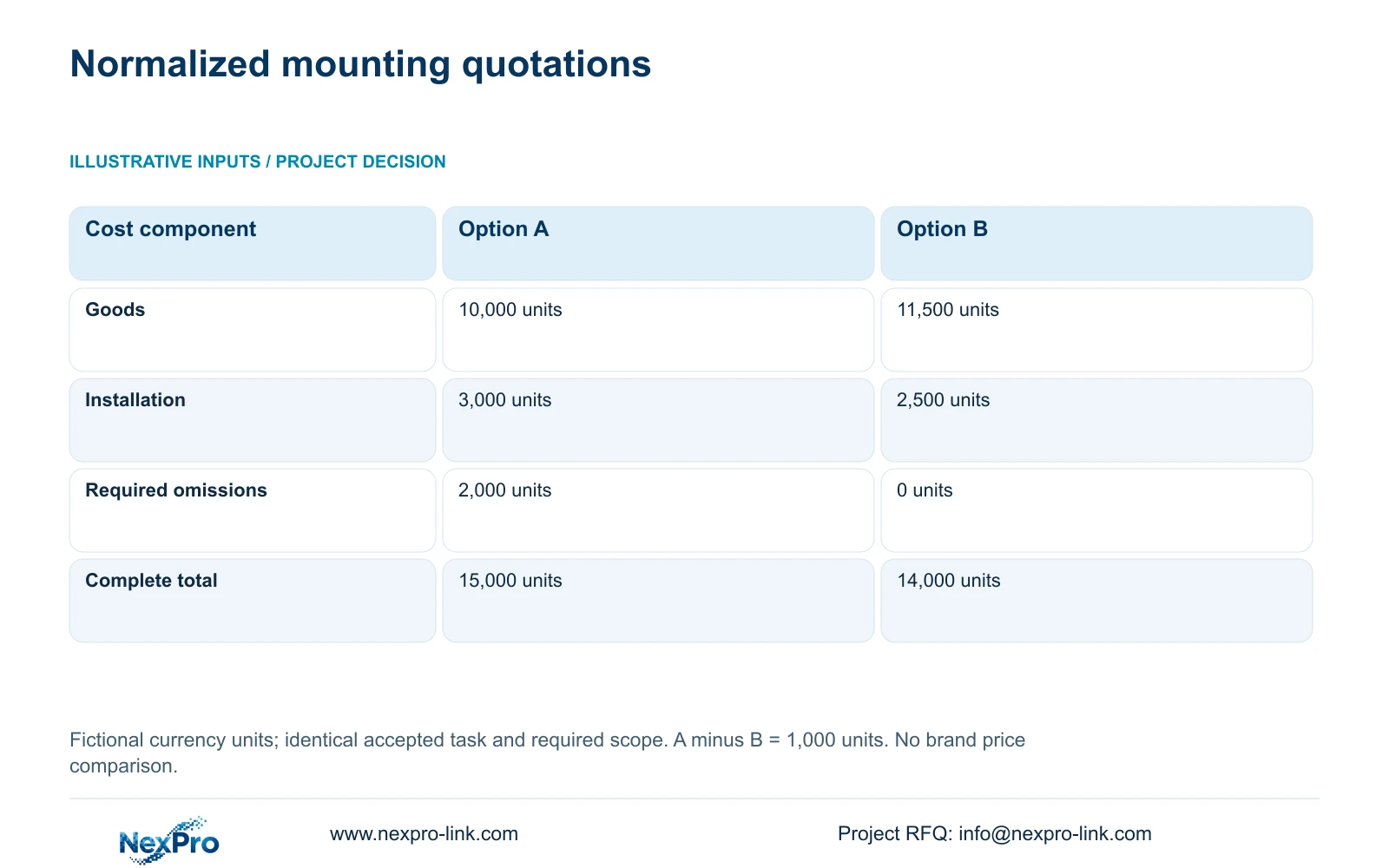
Use the accepted viewpoint and installation boundary to normalize the bids. The following example uses fictional currency units, with no brand prices. Option A quotes goods at 10,000 units and installation at 3,000 units, but omits 2,000 units of required work. Option B quotes goods at 11,500 units and installation at 2,500 units, with no required omitted scope in this example.
Apply normalized_total = goods + installation + required_omitted_items. Option A therefore totals 10,000 + 3,000 + 2,000 = 15,000 units; Option B totals 11,500 + 2,500 + 0 = 14,000 units. The difference, A_total minus B_total, is 1,000 units. The decisive difference is the omitted work: the lower goods quotation produces the higher complete total.
For a mounting comparison, investigate whether those omissions concern the base, compatible bracket, connection enclosure, route extension, protection work or access equipment. Do not assign the fictional 2,000 units to a specific activity without an actual quotation. Replace every monetary input with same-date, same-quantity, same-currency and same-delivery-scope offers. Unresolved required work stays visible as an exclusion; it cannot support a claimed saving.
| Cost component | Option A | Option B |
|---|---|---|
| Quoted goods | 10,000 units | 11,500 units |
| Installation | 3,000 units | 2,500 units |
| Required omitted scope | 2,000 units | 0 units |
| Normalized total | 15,000 units | 14,000 units |
Section 05
Use the wall when it passes the same acceptance test
Recommend the wall option when the accepted view, fixing arrangement, continuous cable route and service access all fit. It avoids introducing a standalone support solely because a pole appears more flexible on a sketch. The owner should approve a representative view, while the engineer confirms the mounting interfaces and the quantity surveyor checks the complete included work.
Choose the pole when it provides necessary coverage that the wall cannot deliver, subject to approval of its supporting and electrical details. Record the specific benefit, such as maintaining the dispatch handover view when loads occupy the wall's sightline. Also record the additional foundation, route and maintenance scope. A pole should have a documented operational reason that survives comparison with another feasible wall position.
Reopen the choice if traffic routes, stack locations, mounting height or the access method changes. A longer copper route may also require a different network arrangement, with its own equipment and local power boundary. Keep mandatory camera brands or specialist requirements intact during this review. Comparing supports does not justify substituting a camera that cannot meet the original scene or environmental requirement.
Section 06
Issue a mounting schedule that suppliers can price
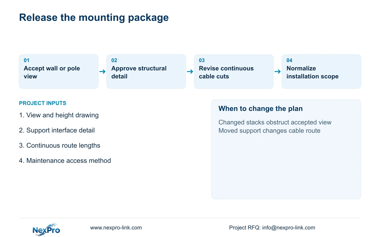
Release one schedule row for each affected camera position. Include the project tag, observation task, approved support type, mounting height, bracket interface, route reference and service-access method. Attach the relevant structural detail by revision. Separate retained structures from supplied accessories and installer-provided work so each bidder prices the same boundary.
The purchasing package should carry a route-length schedule, revised reel-cut allocation and link-budget check where applicable. State cable construction requirements separately from patch-panel and module quantities. If a direct-plug or MPTL arrangement is selected instead of the two-module permanent-link assumption in CASE01, revise the termination materials and testing scope together.
NexPro-Link's BOQ and tender support can help coordinate model matching, equipment quantities and technical deviations against this schedule. Its factory project supply scope provides a route for discussing related equipment and project packing. Structural approval, local installation and final acceptance remain with the appointed project parties. Require the quotation to identify outstanding interfaces before releasing the mounting package.
Section 07
Buyer questions
Can an existing pole be treated as a free mounting location? Only after its suitability and access have been reviewed. Record permission to use it, the proposed attachment, existing services and any modification work. A retained support may still require a new bracket, route, enclosure or service-access allowance.
Should the pole and camera be purchased together? They can share a procurement package if the camera interface and site-approved support detail are settled. Keep responsibility for foundation design and installation explicit. Coordinated purchasing does not make the equipment supplier responsible for unassigned civil work.
Does moving a camera require replacing its entire cable? First check whether the existing continuous link can reach the approved position with appropriate service allowance. If it cannot, specify a suitable new route or approved connection arrangement and its testing scope. Do not assume loose offcuts can extend a permanent link.
Section 08
Request a comparable mounting package
Send the proposed wall and pole positions, required scene views and heights, continuous cable routes, and site mounting/access constraints to info@nexpro-link.com for a coordinated equipment and quotation-scope discussion.
Engineering references
These sources support the general planning principles. Always use the selected product's current datasheet and applicable project standards for final design.