After installation, compare each accepted as-built route with its priced continuous cut. Separate additional installed length, returned uncut stock and unusable remnants.
Section 01
Measure the continuous route to each endpoint
After installation, compare each accepted as-built route with its priced continuous cut. Separate additional installed length, returned uncut stock and unusable remnants. Refer an overlength link for redesign/testing review rather than hiding it inside aggregate metres. This reconciliation explains the variation without treating leftover cable as a completed spare link.
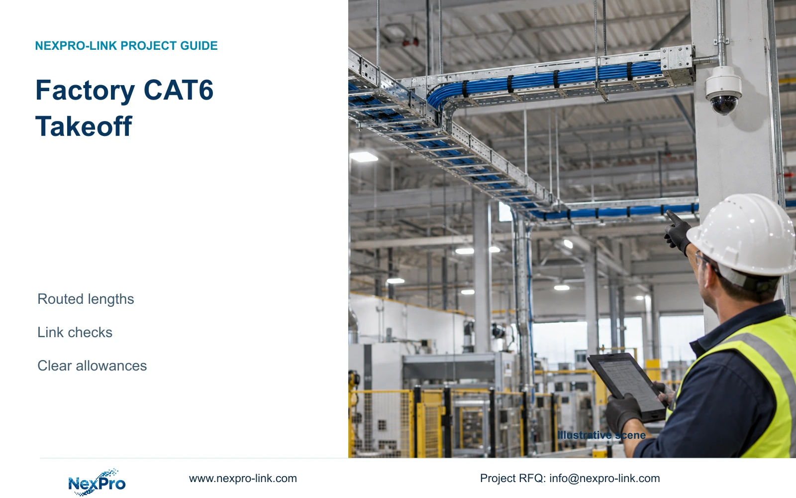
A factory CAT6 takeoff should measure the continuous installation route for every link, including horizontal tray travel, vertical rises, drops and explicit endpoint allowances. Record each length against a camera and cabinet identifier before calculating the total. An average distance is useful for an early allowance, but it cannot establish whether every run fits the selected link design or can be cut from the purchased reels.
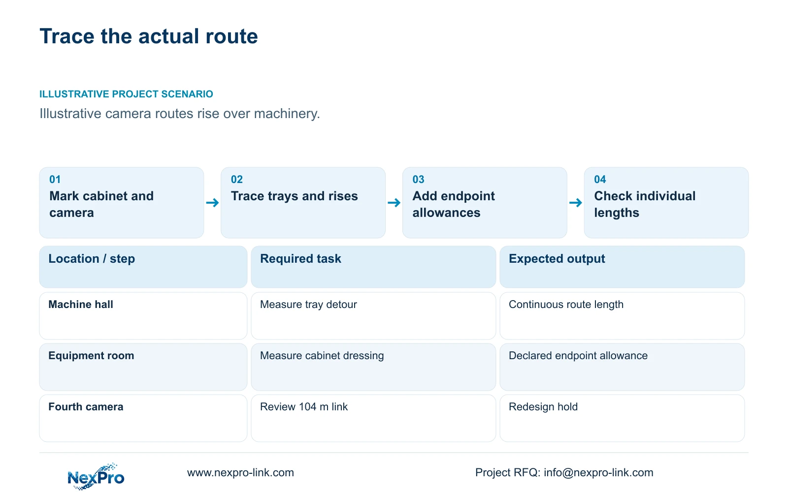
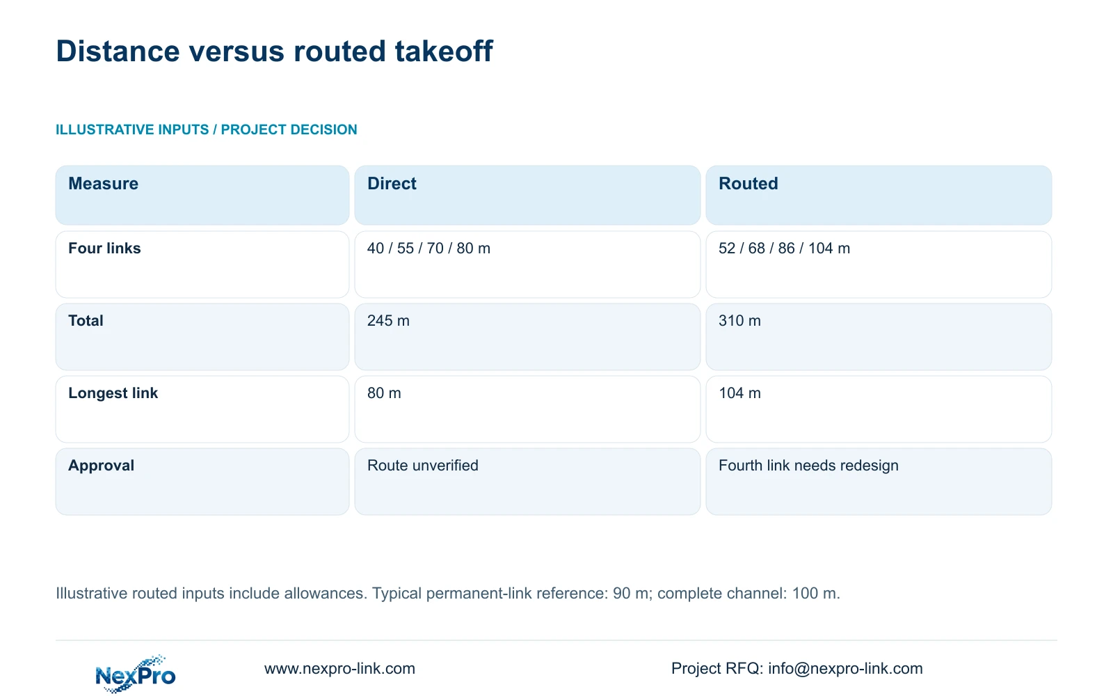
Illustrative project scenario: The estimator has point-to-rack distances, but cable follows trays and rises over machinery. Assume four proposed camera links have direct distances of 40, 55, 70 and 80 m. Following the planned installation paths and including the stated allowances produces lengths of 52, 68, 86 and 104 m. These are planning inputs, not measurements from a delivered customer project.
Trace the route on a coordinated drawing, then check elevations and cabinet entry positions with the installation team. A ceiling plan alone may omit the ascent from a low cabinet or the descent to a wall-mounted camera. Give uncertain segments a visible status so procurement can distinguish a measured route from a provisional one.
Section 02
Keep endpoint allowances separate from material reserve
Use separate schedule columns for horizontal travel, vertical travel, cabinet dressing and camera-end service length. Their sum becomes the required continuous cut. This lets the engineer change a mounting height or cabinet position without applying another blanket percentage to an already adjusted length. It also tells the installer where the extra cable belongs.
Service cable remains part of the installed run and its applicable length assessment. Reel remnants are material left after cutting. Deliberate reserve is stock purchased for approved changes or replacement work. Combining these quantities under one waste percentage makes it difficult to explain why an order increased or whether the remaining cable can serve a particular future link.
CASE01 provides a separate 32-camera CNC planning baseline: routes of 35 to 70 m receive a declared 6 m combined service and termination allowance, creating 41 to 76 m continuous cuts. That 6 m is specific to the example. Do not apply it again to the four-link illustration, whose routed inputs already include installation allowances.
Section 03
Check the permanent link before approving the total
Fluke Networks guidance distinguishes a typical 90 m copper permanent link from a 100 m complete channel. The channel includes the relevant patch cords; the two figures describe different boundaries. Identify the intended termination arrangement and applicable test configuration before using either number to approve a camera run.
The planned 104 m permanent link therefore needs a design decision. Consider a shorter approved route, a relocated cabinet or a fibre-fed local access node. Removing necessary service length simply to make the schedule look compliant creates an installation problem. Changing the category label also does not, by itself, resolve this ordinary permanent-link length issue.
Assign the engineer responsibility for the revised route and link boundary, and the local installer responsibility for confirming access and termination practicality. Procurement should hold the affected cut until the revision is accepted. If the design uses a direct camera plug or modular plug terminated link, specify that arrangement and its testing method explicitly rather than silently treating it as a module-ended permanent link.
Section 04
Compare quantities and the longest link together
For the four-link illustration, total_m = sum(individual_link_lengths). The direct estimate is 40 + 55 + 70 + 80 = 245 m. The routed takeoff is 52 + 68 + 86 + 104 = 310 m. The difference is 65 m, but the more consequential finding is the individual 104 m run.
Both totals are arithmetic planning results. The direct estimate does not demonstrate that the installed links meet the chosen boundary. The routed schedule reveals an unresolved link even though the other three planned lengths remain below the typical 90 m reference. Correct that link before using 310 m as a final purchasing quantity.
Dividing a total by reel length only establishes a material lower bound. It does not allocate complete cuts. After the route correction, produce a reel assignment with link IDs and remaining lengths. Keep separately specified cable constructions in separate allocations so an indoor remnant is not counted as available stock for an outdoor run.
| Measure | Direct estimate | Routed takeoff |
|---|---|---|
| Individual lengths | 40 / 55 / 70 / 80 m | 52 / 68 / 86 / 104 m |
| Total cable | 245 m | 310 m |
| Longest planned link | 80 m | 104 m |
| Permanent-link decision | Installed suitability unproven | Fourth link needs redesign |
Section 05
Choose the revision that preserves access and maintainability
Prefer a routed, individually checked schedule over the direct-distance estimate. For the fourth link, a cabinet relocation is worth considering when suitable space, power and service access are available nearer the endpoint. The revision must include the changed cable route and cabinet connections, rather than treating the cabinet as a movable symbol with no downstream consequences.
A fibre-fed local node becomes an alternative when the shorter copper arrangement would interfere with production access or create unsuitable cabinet placement. Include optics, local switching and the local power boundary in that comparison. A central UPS does not protect a remote AC-fed switch unless that switch is actually on its protected circuit.
CASE01's 32 links total 1,872 m and have a feasible seven-reel allocation using 305 m reels. Its lengths are already checked against the stated planning boundary. Those figures demonstrate the next stage after takeoff; they are a separate scope and should not be added to the four-link illustration. Compare supplier proposals against the same approved route revision and installation responsibilities.
Section 06
Issue a cable schedule that procurement can price
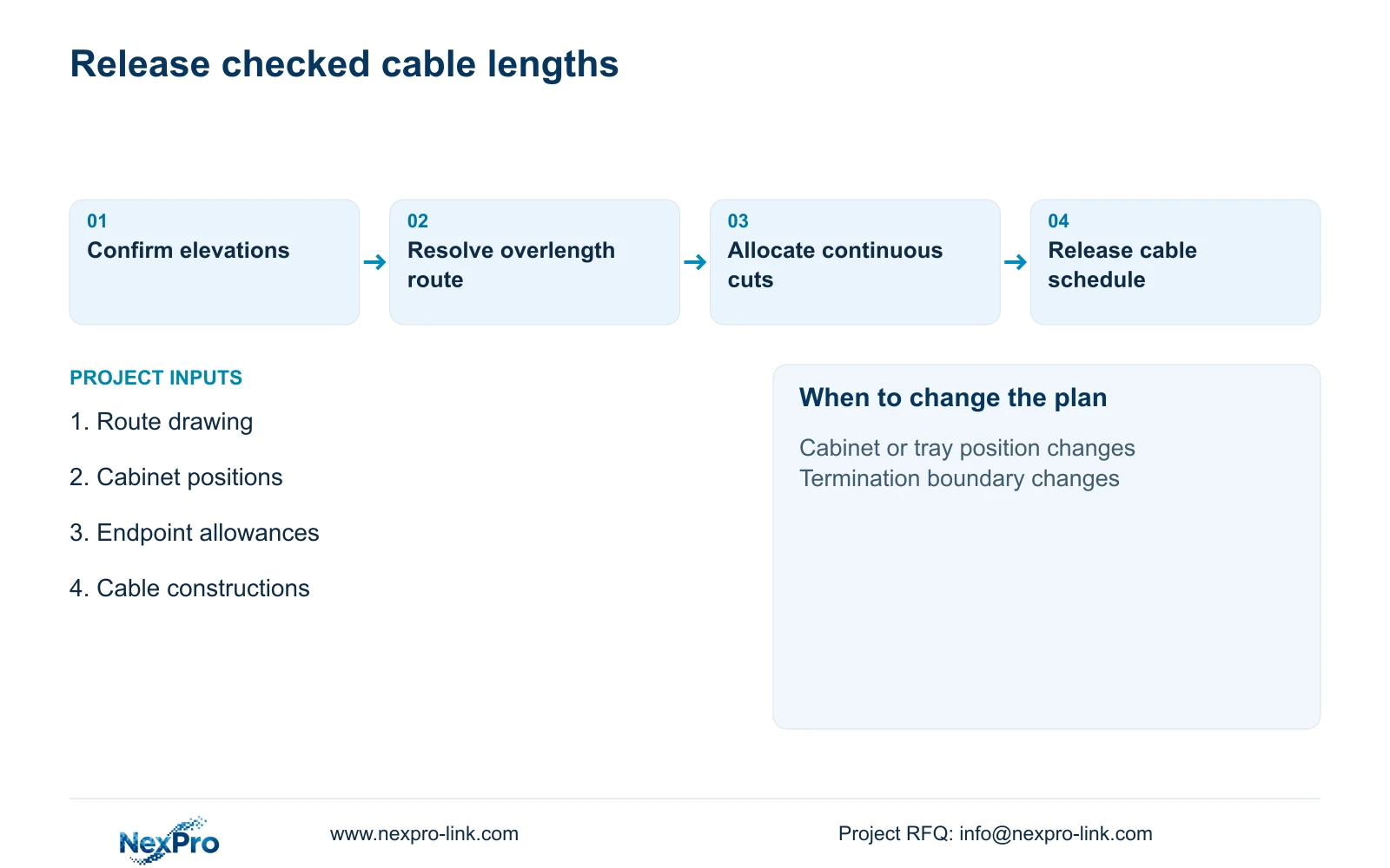
The release package should identify every link, cabinet, cable construction, required cut and termination method. Attach the accepted route drawing and flag items supplied by the local contractor, such as trays, supports, penetrations and testing. A cable quantity without those boundaries leaves bidders to price different installation assumptions.
NexPro-Link's Structured Cabling references include the SP5648 Cat6 48-port patch panel and DT968MX Cat6 tool-less module. They are termination components, not bulk cable reel identifiers. Select their quantities from the cabinet and endpoint arrangement, then obtain the exact cable specification separately. Compatible components and installation remain part of the complete link assessment.
NexPro-Link's BOQ and Tender Support scope can help coordinate the equipment schedule, technical documents and quotation deviations. Keep the local route approval and installation work assigned to the project team. Require any proposed substitution to show its effect on continuous lengths, termination counts and the test boundary before accepting a revised material total.
Section 07
Buyer questions
Can we order cable while one route remains provisional? Release confirmed links separately if their cable construction and cut assignments are stable. Keep the provisional link out of the final cutting instructions and state whether any purchased stock is an approved contingency.
Should measured tester length replace the drawing takeoff? Use the takeoff for planning and the correctly configured test record for the installed link. Investigate material differences and update the as-built schedule; do not assume the two records describe identical boundaries.
Can a spare patch-panel port solve an overlength run? No. A spare port provides connection capacity at its cabinet. The route length still needs correction or a different approved network arrangement.
Section 08
Request a routed takeoff review
Send your link-by-link route lengths, cabinet locations, endpoint allowance basis and cable exposure requirements to info@nexpro-link.com to discuss the cable schedule and associated supply scope.
Engineering references
These sources support the general planning principles. Always use the selected product's current datasheet and applicable project standards for final design.