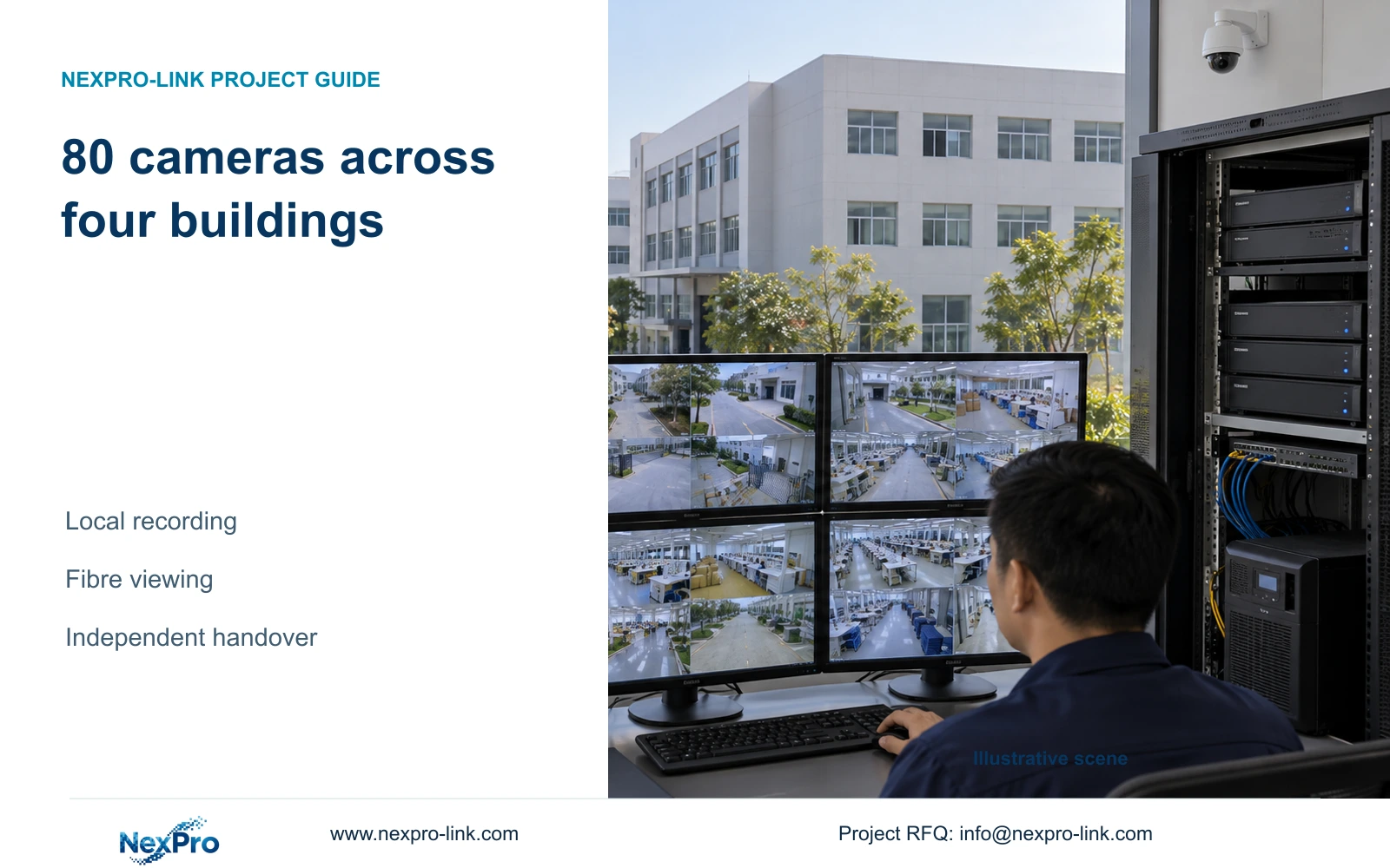
An 80-camera garment campus needs four complete local recording paths when evidence must survive a backbone interruption. Central viewing remains a separate service with its own permissions, traffic and display choices.
Section 01
Make each building's recording task independently complete
Use protected building-level recording for an 80-camera garment campus when each building must retain evidence during a backbone interruption. Allocate cameras, drives and power by building. Central supervision can retrieve permitted footage over the backbone, but it should not become an unnecessary dependency in the local camera-to-recorder path.
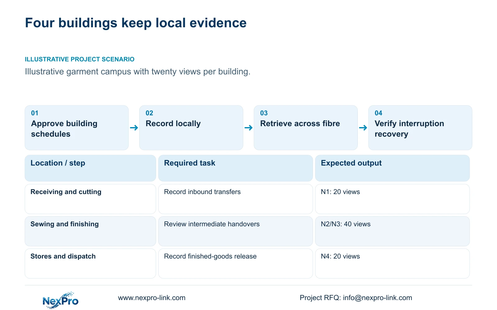
Illustrative project scenario: Four garment-campus buildings each need twenty security views and local retention during a backbone interruption. N1 covers receiving/cutting, N2 sewing transfers, N3 finishing/packing and N4 stores/dispatch. The reference contains eighty ordinary-area views, no specialist positions and a 30-day continuous-recording target.
Approve a separate point schedule for each building, using transfer boundaries and access events rather than dividing cameras by floor area. Identify where a handover moves from one building's view to another and agree consistent location names and time settings. Local recording preserves available footage; it does not guarantee the central desk can view it while the inter-building connection is down.
Section 02
Require every building to meet retention with its own drives
At an assumed 4 Mbps average per camera, each twenty-camera recorder receives 80 Mbps. Video_TB = 20 × 4 × 10^6 × 86400 × 30 / 8 / 10^12 = 25.92 TB per building. Across four nodes, required video is 103.68 TB and required usable capacity with 20% free space is 103.68 / 0.80 = 129.6 TB.
Each node contains four 12 TB drives: 48 TB raw and 45.6 TB after the assumed 95% formatting factor. Recording_budget = 48 × 0.95 × 0.80 = 36.48 TB per node. Compare each building's 25.92 TB directly with its own 36.48 TB budget. An underfilled recorder elsewhere cannot repair a local capacity shortfall.
NexPro-NVR4449-4K provides the 320 Mbps input and four-bay reference, with up to 18 TB per drive. Confirm the case's supported 5MP-class streams against its separate 49×5MP and 9×4K summary modes. Ordinary BL/DM candidates list 2880×1620 output. Validate actual stream settings, drive models and playback separately; the four-drive arrangement does not establish RAID or cross-building failover.
Section 03
Keep local recording traffic off unnecessary backbone routes
Each node has three access groups: SW1 and SW2 serve eight cameras each, and SW3 serves four. N1 through N4 repeat that allocation, producing twelve groups. With assumed 12 W device demand, the eight-camera groups require 96 W at devices, 106.6667 W PSE output after division by 0.90, and 133.3333 W budget after division by 0.80.
The four-camera groups require 48 W at devices, 53.3333 W PSE output and 66.6667 W budget. Complete AC consumption is (PSE_output_W + 15) / 0.90: 135.1852 W for an eight-camera group and 75.9259 W for a four-camera group. Obtain selected-camera maxima and actual switch budgets before treating any model as compliant. Check the eight-camera and four-camera groups against each selected switch's negotiated PoE allocations as well as the aggregate draw estimate; class-reserving admission may require more budget than these load-based figures.
The campus recording total is 320 Mbps, but each local recorder receives 80 Mbps. Size each backbone segment from the streams, playback sessions and exports that actually cross it, including approved peak demand. Keep management paths and production-control access explicit. Demonstrate local recording during an approved backbone isolation test, then verify central retrieval after reconnection.
Section 04
Compare display options without combining four power circuits
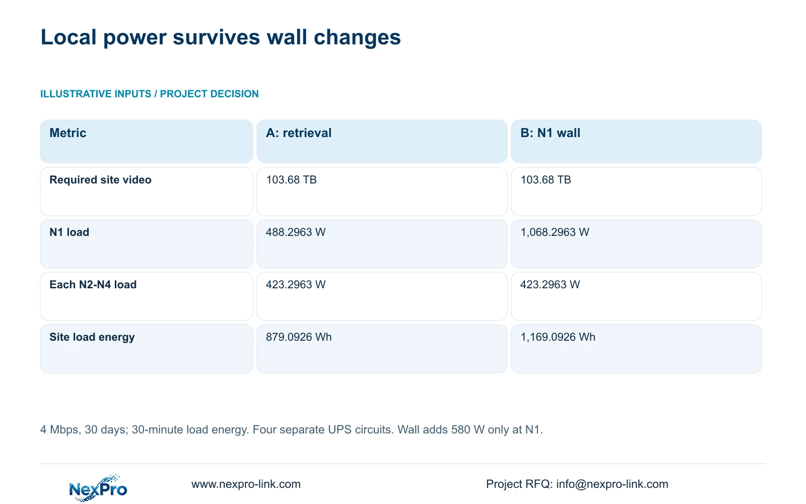
Using complete switch AC inputs, a 30 W recorder and four drives at 8 W each, N2, N3 and N4 each total 423.2963 W including a 15 W link terminal. N1 totals 488.2963 W because its reference includes a 25 W core, 15 W router and 40 W retrieval display instead. Site demand for option A is 1,758.1852 W.
Option B adds four assumed 120 W LCD panels and a 100 W decoder at N1. N1 rises to 1,068.2963 W, while the other three nodes remain unchanged; total demand becomes 2,338.1852 W. NX-VP-5535 is an LCD reference, and its assumed panel load must be replaced by selected-equipment data. A wall changes central visibility, not each building's retention requirement.
Check rated_W ≥ load_W / 0.80 and rated_VA ≥ load_W / (0.90 × 0.80) at every node. SP1KR(S), 1 kVA/900 W, is A's capacity candidate throughout; B changes N1 to SP2KR(S), 2 kVA/1800 W. Load_Wh = load_W × 30 / 60 yields the table totals, with N1 at 244.1481/534.1481 Wh and each other node at 211.6481 Wh. Batteries require local runtime evidence.
| Metric | A: retrieval screen | B: add N1 wall |
|---|---|---|
| Site required video | 103.68 TB | 103.68 TB |
| N1 protected demand | 488.2963 W | 1,068.2963 W |
| Each N2-N4 demand | 423.2963 W | 423.2963 W |
| Site protected demand | 1,758.1852 W | 2,338.1852 W |
| 30-minute site load energy | 879.0926 Wh | 1,169.0926 Wh |
Section 05
Allocate cable cuts and panels to their destination buildings
The eighty new camera links use assumed 41 to 76 m continuous runs, including a declared 6 m service/termination allowance. Total cable is 4,520 m. The arithmetic lower bound is ceil(4,520 / 305) = 15 reels, while the supplied feasible cutting allocation uses sixteen 305 m reels. Budget the allocated plan unless a revised complete plan proves another quantity workable.
Four 76 m runs fit one reel at 304 m, but the remaining mix cannot be approved from total metres alone. The supplied final reel uses three 41 m runs, or 123 m. Its remaining length is residue, not an automatic spare for every location. Keep camera IDs, destination building and reel allocations available to the installation crew.
The module-ended assumption yields 160 modules and twenty occupied panel ports per building. SP5648 is a 48-port patch-panel reference, allocated by actual cabinet layout rather than eighty site ports divided globally. Inter-building fibre needs its own route, optics and termination schedule. Confirm local link tests, outdoor entries, containment and building-specific installation access.
Section 06
Approve local handover and central operation as separate milestones
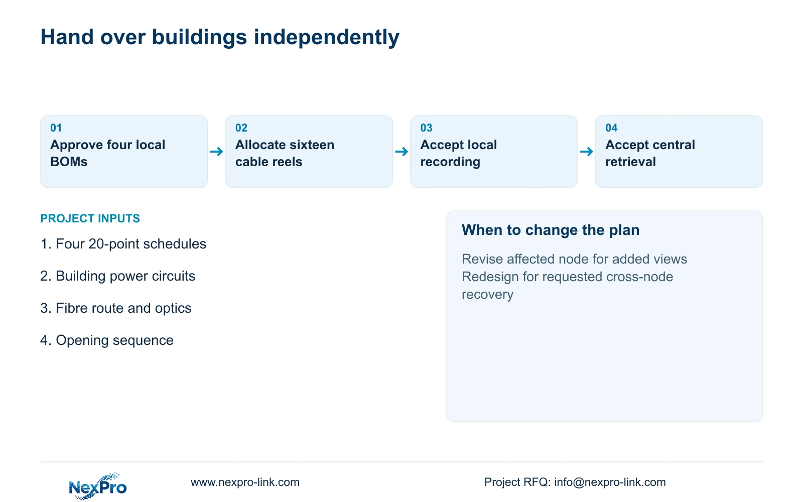
The equipment baseline contains eighty ordinary cameras, four recorders, sixteen compatible 12 TB drives, twelve qualified switches and four UPS configurations. Add one retrieval display, sixteen cable reels and the drawing-derived cabinet, mounting and termination scope. Price the wall separately so central display work does not delay a building's recording handover.
Give each building a local acceptance record covering its views, retention configuration, power circuit and usable exports. The campus acceptance then checks authorised access to all four recorders, cross-building event retrieval and recovery after a backbone interruption. This separates incomplete central supervision from a fault in an otherwise functioning local recorder.
NexPro-Link's project and BOQ support can coordinate building-labelled equipment schedules and technical documents. Compare other packages against the same four independent recording tasks and local service boundaries. Choose a different architecture if the owner requires cross-node recovery or a mandatory central platform, then recalculate its real traffic, storage and power dependencies.
Section 07
Buyer questions
Will central footage reappear automatically after a fibre outage? Local recordings may remain available for later retrieval, but automatic central replication is not specified. Agree the reconnection and retrieval workflow on the selected client platform.
Can one building open before the control room is complete? Yes, if its approved local recording and retrieval arrangements are operational and accepted. Define an interim authorised retrieval method rather than relying on unfinished central equipment.
Can spare disk space be pooled between these recorders? No pooling is assumed. Each building must meet its own retention target; a shared storage architecture would be a different design requiring supported equipment and new calculations.
Section 08
Define four building handover packages
Send the four building camera schedules, backbone route diagram, per-building retention/backup targets, and opening sequence to info@nexpro-link.com for a building-level equipment proposal.
Engineering references
These sources support the general planning principles. Always use the selected product's current datasheet and applicable project standards for final design.
- User BL2812M series product specification
- User DM2812M series product specification
- NexPro-NVR4449-4K
- NexPro-Link rack online UPS
- NexPro-Link Structured Cabling
- NexPro-Link Factory & Warehouse project supply
- NexPro-Link BOQ & Tender Support
- NexPro-Link NX-VP-5535 LCD video wall panel
- NexPro-Link NX-VD-4K16 network video decoder
- Microchip: Next-Generation PoE IEEE 802.3bt White Paper