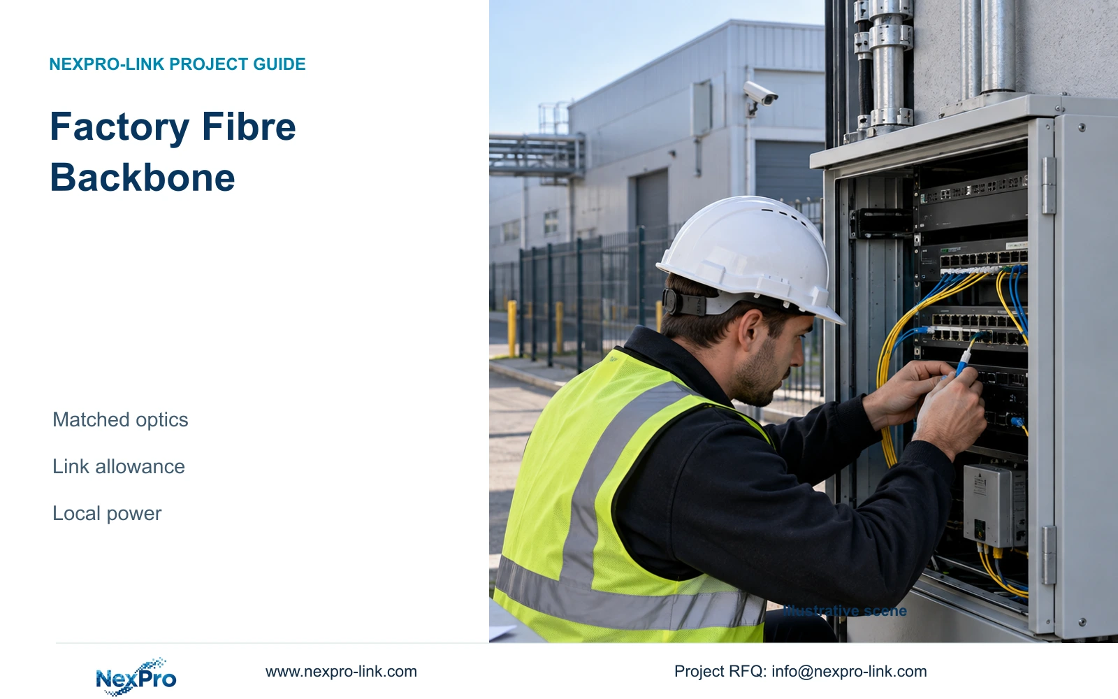
A factory fibre backbone needs matched optics and documented loss allowance at both ends. Its remote access switch still needs local power, whether recordings stay in the building or cross the backbone.
Section 01
Specify the optical path and remote supply together
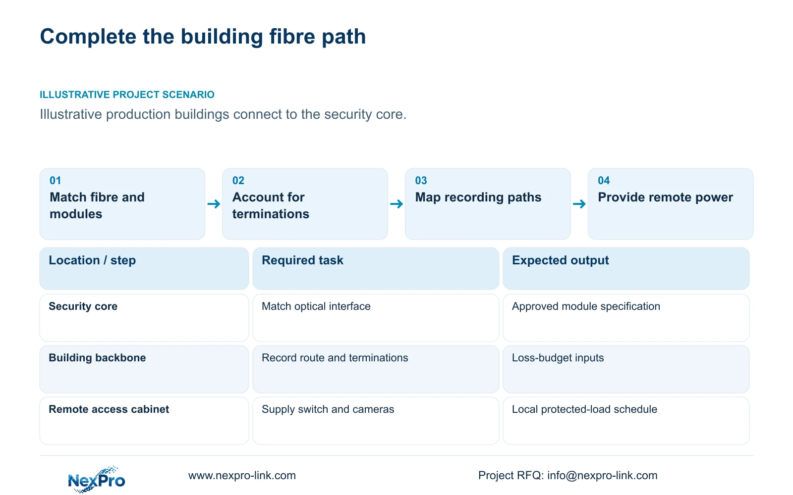
Specify a factory fibre backbone as a complete path: fibre type, matched transceivers, compatible switch interfaces, connectors, terminations and optical loss allowance. Document remote power separately. Fibre carries the data connection; it does not supply the remote camera switch with PoE power.
Illustrative project scenario: Separate production buildings need a reliable connection to the security core. Use CASE01's 32-camera recording task as a sizing reference, while treating inter-building access nodes as a planning extension. The original reference has one electrical node and does not establish building distances, existing fibre type or remote backup supplies.
Start with an end-to-end schedule for each proposed building link. Identify what exists and what must be supplied at both ends. Missing distance or optical ratings should remain explicit procurement inputs. A provisional design can define the required roles without inventing a transceiver model or an unsupported optical reach.
Section 02
Check optical allowance against the complete installed path
Request the selected modules' transmit and receive specifications and the supported fibre arrangement. Confirm interface compatibility with the proposed switches, fibre type, operating wavelength and connector arrangement. For a paired single-fibre design, obtain the exact compatible pairing rather than assuming two identically named modules form a link.
Use a documented budget method: available optical budget in dB = minimum transmit power in dBm minus receiver sensitivity in dBm. Compare this with fibre attenuation, connector and splice losses, plus the agreed design margin. Calculate each transmission direction using its own transmitter and receiver ratings; one passing direction cannot approve the reverse path. Also check the selected receiver's permitted input range. The supplied package contains no numerical module ratings or measured path losses, so no defensible dB result can be assigned here.
The engineer should issue the method and required evidence; the optical equipment supplier returns exact ratings; the installer records the accepted path and test result. A nominal distance label is insufficient when the installed path adds terminations or uses retained infrastructure with unknown condition.
Section 03
Include patching and maintenance access in the backbone scope
Count the fibre route, termination points, splice work, patch leads and labelled interfaces together. Record the cores used and any approved spare allocation. Check cabinet space and access for handling the selected components, then assign responsibility for testing and restoring the path after maintenance.
Keep copper camera terminations distinct from optical backbone components. NexPro-Link's Structured Cabling page identifies the SP5648 Cat6 48-port patch panel and DT968MX tool-less module. They may serve relevant local copper links, but they are not optical distribution hardware or bulk fibre cable references.
Price retained-path verification separately from new installation where their responsibilities differ. Add each termination to the optical budget worksheet rather than treating patching as a purely commercial accessory. The procurement team then sees how a route revision can change both material quantities and the evidence needed for link approval.
Section 04
Determine whether main streams cross the building link
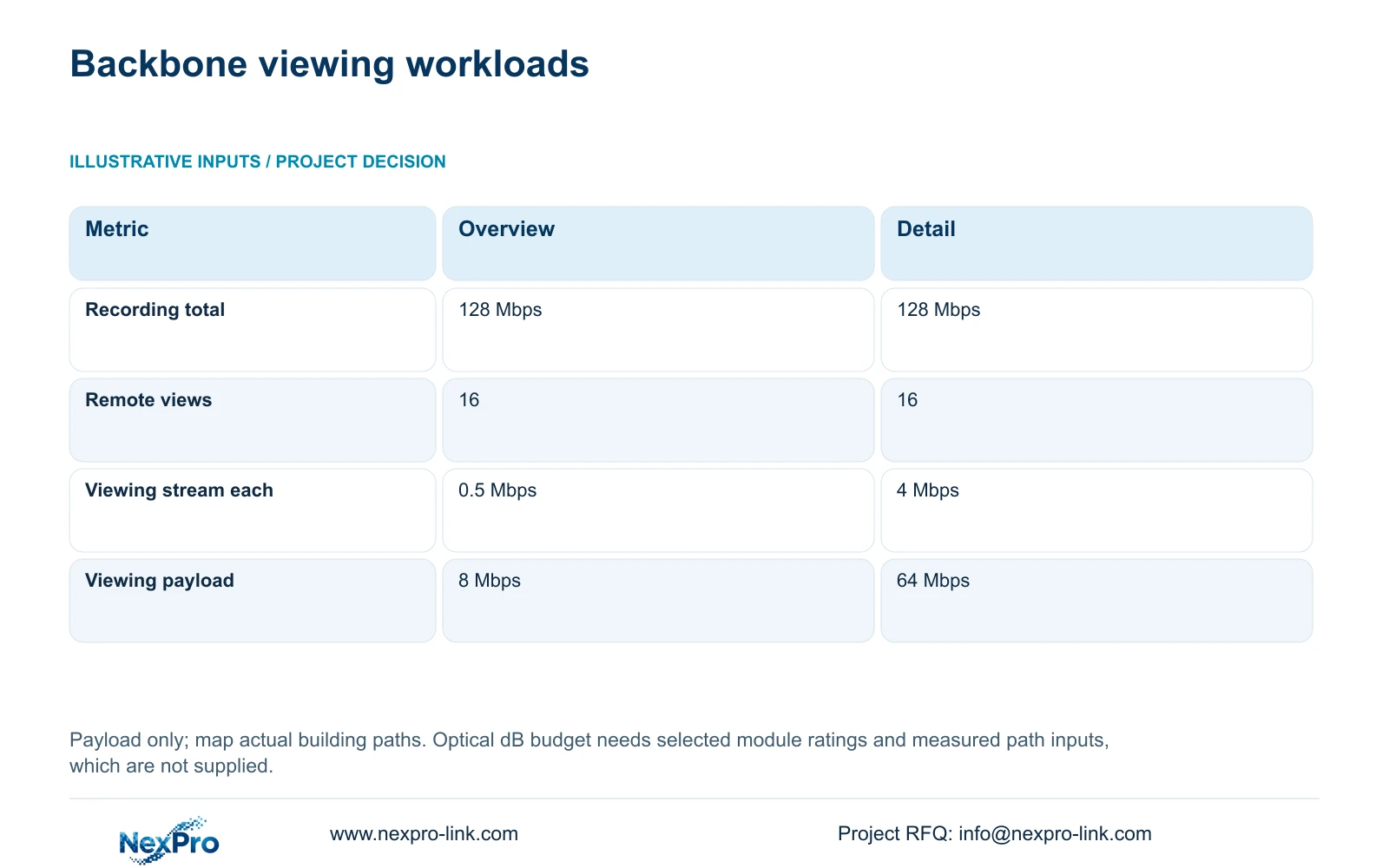
The supplied traffic comparison fixes recorder_Mbps = 32 × 4 = 128 Mbps. For 16 simultaneous operator views, viewing_Mbps = 16 × stream_Mbps gives 8 Mbps at 0.5 Mbps each or 64 Mbps at 4 Mbps each. Local main-stream recording quality remains unchanged in both options.
If recorders are local to production buildings, the link to the security core may carry approved viewing traffic while the main streams remain within their local recording paths. If the recorder is central, the relevant cameras' main streams cross the backbone. The 128 Mbps total is not automatically present on every building fibre.
The decisive difference between the two viewing options is backbone payload where those sessions traverse it. Prefer the overview setting when supported and adequate for the operator task. Add protocol overhead, playback, exports and shared services on actual interfaces. Traffic capacity and optical loss are independent checks; passing one cannot establish the other.
| Metric | Overview viewing | Detail viewing |
|---|---|---|
| Aggregate recording input | 128 Mbps | 128 Mbps |
| Concurrent remote views | 16 | 16 |
| Viewing stream each | 0.5 Mbps | 4 Mbps |
| Viewing payload | 8 Mbps | 64 Mbps |
| Recording quality changed | No | No |
Section 05
Protect every powered endpoint needed for the service
Show local mains, the selected protected supply, remote switch and camera power connections beside the fibre data path. Include optical modules or separately powered conversion equipment in the appropriate load list. Central backup protection alone cannot establish continuity for a remote cabinet on another electrical circuit.
CASE01 estimates 135.1852 W AC demand for an eight-camera switch group using assumed camera demand, delivery and conversion factors. Use that only to understand the dependency method, not as the measured load of a new building node. Replace it with selected equipment data and include any additional local devices before sizing backup.
The NexPro-Link rack online UPS source lists SP1KR(S) at 1 kVA/900 W, SP2KR(S) at 2 kVA/1800 W and SP3KR(S) at 3 kVA/2700 W. These are capacity references. Select the actual supply and battery arrangement from the node load, voltage and required duration; no model rating or load-side Wh calculation proves runtime.
Section 06
Accept the optical link and recording service separately
Recommend the complete optical and local-power package when the approved building routes justify fibre. The quotation should identify compatible modules at both ends, fibre and termination scope, switches, protected local supplies and tests. A camera-only offer omitting these dependencies cannot be compared with a complete working backbone.
NexPro-Link's BOQ and Tender Support scope can coordinate equipment matching and document gaps in the proposed package. Plant IT approves management and permitted traffic boundaries, with NIST SP 800-82 Rev.3 providing the supplied OT-security context. Local specialists confirm the physical installation and electrical responsibilities.
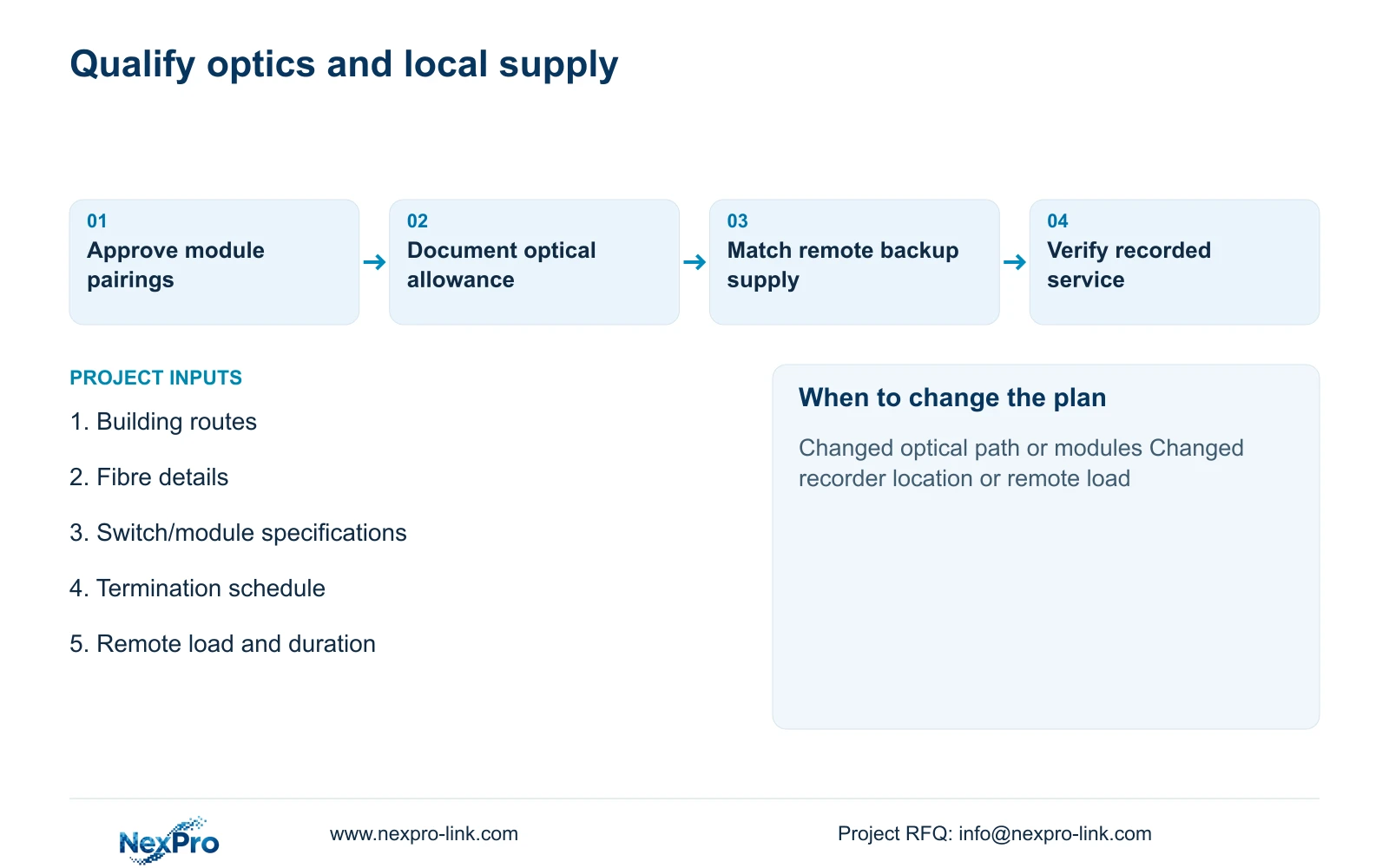
Acceptance should retain optical-path records and demonstrate recording, viewing and retrieval under the approved workload. Check local power interruption separately from backbone interruption using an authorised plan. Reassess the design when fibre type, module pairing, termination count, recording location or remote load changes. Keep both worksheets current so a later substitution does not leave a technically incomplete link.
Section 07
Buyer questions
Can we reuse existing factory fibre? Potentially. Confirm its type, route, termination condition and accepted test results, then match the proposed optical modules. Existing connectivity alone does not qualify a new optical arrangement.
Does a successful optical link test prove CCTV performance? It supports the physical-path assessment. Verify the actual recording and operator workload separately, including the selected device modes and concurrent retrieval tasks.
Can a spare transceiver be chosen by connector shape alone? No. Preserve the approved interface, optical ratings, fibre compatibility and pairing requirements in the spare specification. The connector is only one matching field.
Section 08
Define a complete building fibre link
Send your building routes and fibre details, proposed switch/transceiver specifications, termination schedule, and remote load with backup objective to info@nexpro-link.com for a coordinated backbone equipment review.
Engineering references
These sources support the general planning principles. Always use the selected product's current datasheet and applicable project standards for final design.