Keep the farm-wide monitoring requirement while not using a general UPS to replace pitch, braking and other dedicated turbine backup.
Section 01
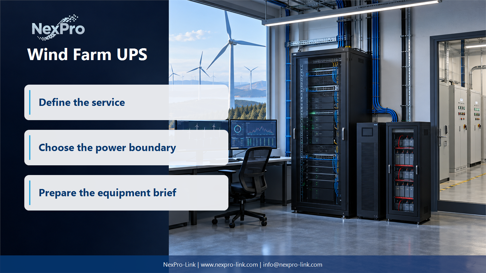
Define What This UPS Supports
Can a general SCADA UPS replace turbine pitch or braking backup? For Wind farm IT leads and communications integrators, the answer must stay inside the project boundary: No. Turbine pitch, braking and other specialized functions follow the turbine manufacturer's system requirements. A general SCADA package should identify only its designated monitoring, networking and support equipment. Keep those supply boundaries separate so an IT continuity solution is not mistaken for a turbine safety-system design. The next step is boundary table: SCADA / network / support / pitch-brake exclusions, using SCADA support scope, remote nodes and turbine-system exclusions.
Capture the answer in the boundary table: scada / network / support / pitch-brake exclusions before equipment is compared. This gives the project team a concrete service target and exposes missing dependencies early.
| Decision area | Project question | Required output |
|---|---|---|
| Define What This UPS Supports | Can a general SCADA UPS replace turbine pitch or braking backup? | Boundary table: SCADA / network / support / pitch-brake exclusions |
| Map Distributed Nodes | Why should remote nodes be listed individually? | Node map: location / source / load / communication / access |
| Plan for Environmental Exposure | What environmental information belongs in selection? | Environment schedule: location / ambient / vibration / enclosure |
Section 02
Map Distributed Nodes
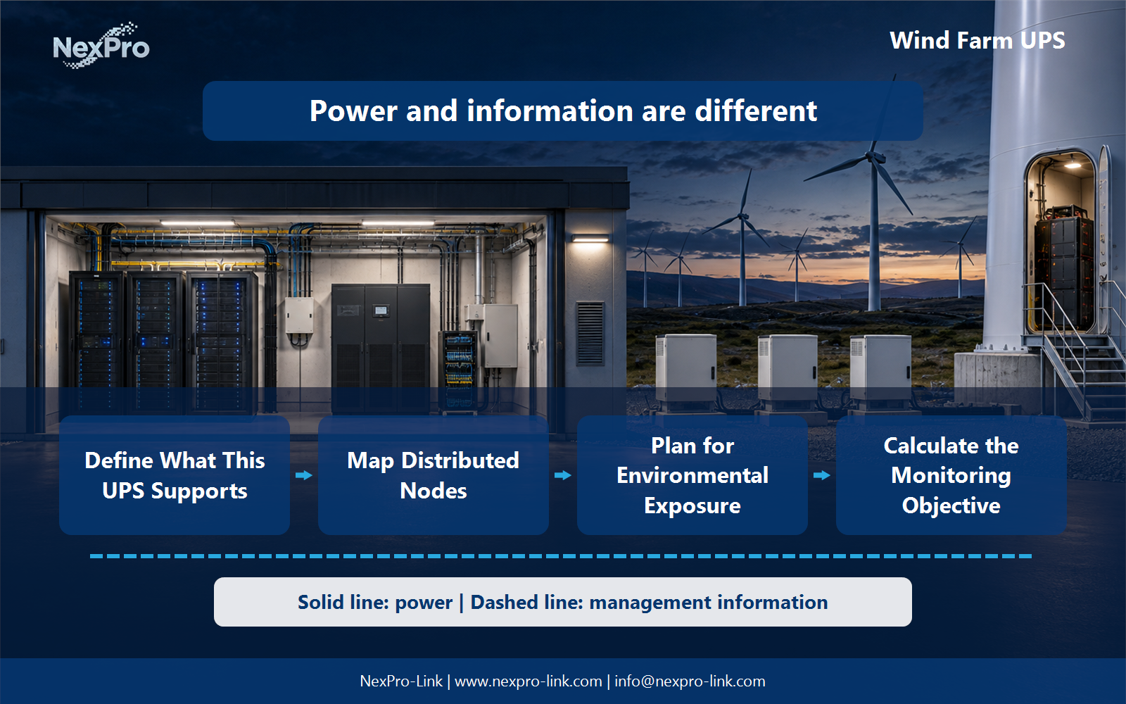
They can have different power sources, environments and communication dependencies. Map each node required for the selected monitoring objective. A control-center UPS does not protect remote equipment unless its actual supply arrangement provides the required backup.
Use the node map: location / source / load / communication / access to keep real interfaces and operating states visible. Measured demand, equipment limits and future allowances should remain separate entries.
Section 03
Plan for Environmental Exposure
Record the installation's specified temperature, moisture, vibration and service conditions. Locate the equipment within an appropriate enclosure or controlled space. Do not infer suitability for a nacelle, tower or coastal site from a generic industrial description.
Review the environment schedule: location / ambient / vibration / enclosure with the owners of the connected systems. Power continuity only supports the functions that remain connected and available during the event.
- Confirm the answer to: What environmental information belongs in selection?
- Draw electrical power as a solid path and management information as a separate dashed path.
- Keep external services and specialist approvals outside the UPS equipment claim.
Section 04
Calculate the Monitoring Objective
Use the complete monitoring and communication chain for the chosen operating state. Separate source-recovery time from travel or repair time. A realistic objective states what remains functional and for how long, rather than promising indefinite remote visibility.
Document this choice in the budget: device / input w / function / interval, including the condition that triggers it and the person responsible for the response.
Section 05
Preserve Local Event Information
Only where the application and storage arrangement support it. Describe local buffering and later retrieval as explicit platform capabilities. UPS runtime helps maintain those functions, but does not itself add logging, synchronization or reliable data replay.
Test the sequence represented by the event path: capture / local store / communication / retrieval during an approved maintenance window. Record the observations needed to confirm recovery.
Section 06
Prepare a Support-Only RFQ
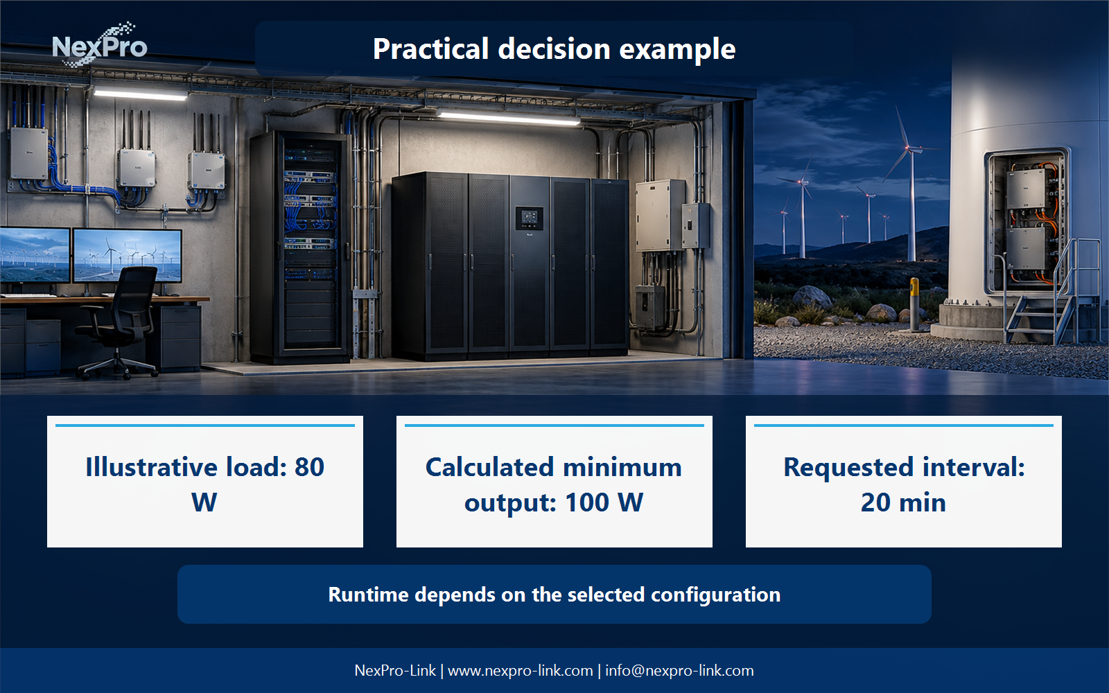
Send the node schedule, support-load demand, environmental limits and required interfaces. NexPro-Link can discuss the relevant UPS scope. Turbine safety functions and manufacturer-specific systems should remain separately specified and supplied through their approved arrangements.
Send the completed rfq: nodes / support loads / environment / interfaces / exclusions with the project request. It is more useful than a capacity number without interfaces, operating states or a defined service boundary.
Engineering references
These sources support the general planning principles. Always use the selected product's current datasheet and applicable project standards for final design.