Separate the control-power boundary from the motor-power boundary, then select the supply path from the load and process requirements.
Section 01
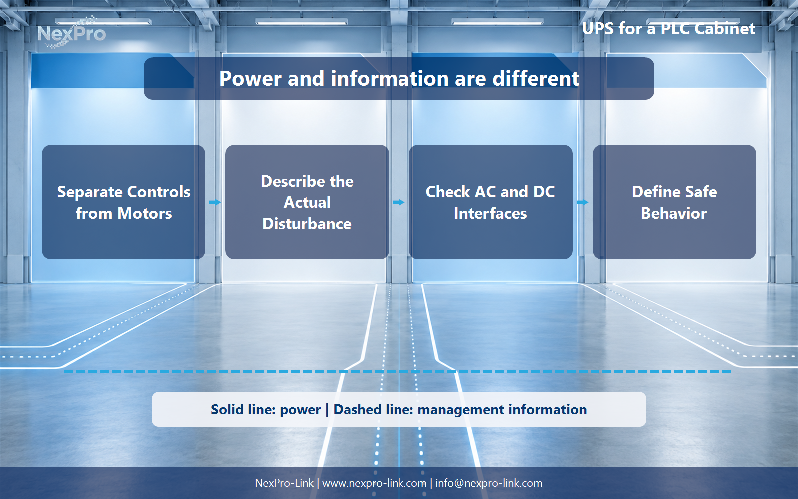
Separate control power from motor power
Separate the control-power boundary from the motor-power boundary, then select the supply path from the load and process requirements.
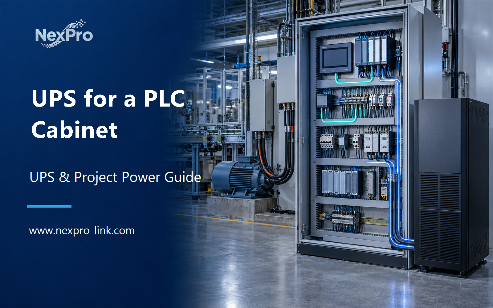
A PLC cabinet may contain controllers, HMI, network switches, sensors, relays, power supplies and drives. The control group often needs continuity, while motors and heaters may need a defined safe stop instead of battery operation. Put these groups on separate lines in the load schedule.
Including a motor circuit by accident can dominate the UPS size and still fail to meet the machine-safety objective. The protected boundary should follow the control sequence and risk assessment, not the physical outline of the cabinet.
| Load group | Typical objective | Design question |
|---|---|---|
| PLC and remote I/O | Maintain logic or finish a safe sequence | Required duration and DC interface |
| HMI and industrial switch | Keep operator and communication path | Can they stop before the PLC? |
| Relays and valves | Reach or hold the safe state | Energize-to-run or de-energize-to-safe? |
| Motors and heaters | Usually stop through the machine design | Are they outside the UPS boundary? |
Section 02
Describe the disturbance the process must tolerate
A brief voltage sag, repeated brownout and complete outage can produce different machine behavior. Record which loads reset, which outputs drop and how long the process can remain controlled. Include generator transfer or contactor chatter when those events are part of the site history.
The UPS objective may be to ride through a short event, complete an orderly stop or preserve controller state for restart. These are different requirements and can lead to different battery and interface choices.
- Use event records or controlled observation where available.
- Separate power continuity from process safety validation.
- Name the required behavior for every output group.
Section 03
Check AC and DC interfaces as one system
Some cabinets accept AC backup ahead of internal power supplies. Others use a DC UPS around a 24 V control bus. Confirm voltage tolerance, inrush, grounding, monitoring, isolation and the behavior of each downstream supply before choosing the interface.
Management contacts and network alarms can report the event, but the PLC logic must define what happens next. Keep the power path and control information path separate in the design documents.
Section 04
Define safe behavior before programming recovery
The machine risk assessment governs the safe state. A UPS should not keep hazardous motion active simply because energy remains available. Define which outputs remain energized, which de-energize and what confirmation is required before restart.
Automatic restart after power returns may be unsuitable. Record the reset, permissive and operator actions needed. Test the control-power sequence with the relevant safety functions under the project's approved commissioning procedure.
Section 05
Buyer questions for UPS for a PLC Cabinet: Control Power, Disturbances and Safe Recovery
For Automation engineers and plant electrical staff, these six checks separate PLC cabinet UPS control power decisions from assumptions that belong to the wider project.
| Buyer question | Practical answer | Project output |
|---|---|---|
| Should a PLC UPS carry the production motors? | Not by default. Identify controllers, I/O, communication and any necessary actuators separately from drives and motors. The power objective may be to retain control and records during a safe stop rather than keep the full machine running. | Cabinet map: controller / I/O / actuator / motor / supply |
| Does an industrial location automatically require one UPS construction? | No. Compare disturbance exposure, temperature, load characteristics and process tolerance. Online operation may be appropriate, but transformer construction alone is not a universal industrial requirement. Develop the selection from the cabinet's actual electrical and environmental constraints. | Exposure table: sag / transient / heat / process effect |
| When should a DC UPS be considered for a PLC? | Consider it when the protected control chain is DC and a compatible DC solution fits the required voltage, current and hold-up function. An AC UPS may protect a wider cabinet supply. Show both boundaries without treating AC kVA and DC output current as interchangeable ratings. | Architecture comparison: AC UPS / AC-DC supply / DC UPS / load |
| Does keeping the PLC powered guarantee machine safety? | No. Safe behavior depends on the machine's validated control and safety architecture. For a project-specific decision, record retain control, stop process and safety system in the function boundary. This keeps the equipment inputs and intended service outcome aligned. | Function boundary: retain control / stop process / safety system |
| How do cabinet conditions affect the proposal? | Use the actual temperature range, ventilation, contamination exposure and maintenance access. Check the chosen equipment's derating and enclosure needs. An industrial label is not a substitute for stating what conditions occur inside the cabinet under normal and outage operation. | Environment schedule: temperature / airflow / contamination / derating |
| What can NexPro-Link receive for a control-power proposal? | Send the control loads, supply interfaces, duration objective and cabinet constraints. NexPro-Link can discuss the equipment portion and available configurations. Machine functional safety and final control design remain separate responsibilities, clearly stated in the supply request. | BOQ fields: power path / output / duration / cabinet / responsibilities |
Section 06
Turn the control load into a project brief
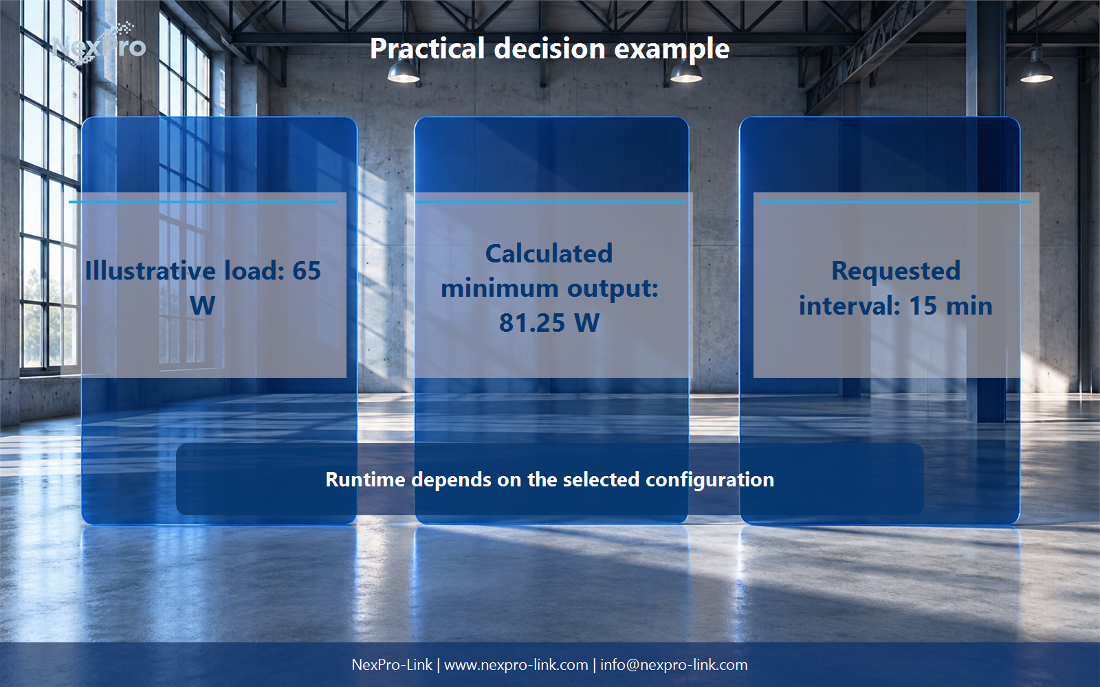
For an illustrative 65 W control group, a 25 percent allowance gives an 81.25 W planning minimum, with a requested 15-minute interval. The calculation is only an output-screening step; actual runtime and DC or AC compatibility need current configuration data.
The brief should include the I/O and HMI loads, control voltage, disturbance objective, supported shutdown or safe-state signal, restart logic, environmental conditions and maintenance access. Keep motors and unrelated cabinet loads clearly outside the protected group unless the design says otherwise.
Engineering references
These sources support the general planning principles. Always use the selected product's current datasheet and applicable project standards for final design.