Split the 48 V DC system from the AC UPS by each device's power input; do not treat the two as one product. Plan the project from the AC and DC load schedule, site autonomy target and environmental limits.
Section 01
Separate the AC and DC load schedules
Split the 48 V DC system from the AC UPS by each device's power input; do not treat the two as one product.
A base station can contain equipment supplied by a DC plant as well as auxiliary equipment that needs AC input. Classify every item by its actual input interface, the supply that serves it and the service that it supports. This keeps a DC plant, rectifier, battery string and AC UPS from being treated as interchangeable parts of one generic backup system.
The split should also identify shared dependencies. A router, switch or maintenance terminal may be small in watts, yet still matter because it carries site visibility or supports a recovery action. Use two schedules and one dependency map so the team can see the boundary between DC-served radio equipment and AC auxiliary loads.
| Item | Input interface | Planned supply boundary | Autonomy record |
|---|---|---|---|
| Radio and related telecom load | Defined DC input | Telecom DC plant and its selected rectifier-battery arrangement | Set from the site service objective |
| Edge computer | AC input | AC UPS or defined AC backup arrangement | Record separately from the DC plant |
| Router and switch | AC input in this example | AC UPS or defined AC backup arrangement | Keep alive while alarm and recovery paths require it |
| Maintenance terminal | AC input | AC auxiliary boundary | May have a shorter operating objective than radio services |
Section 02
Set the site autonomy objective by service
Autonomy is a service instruction, not a battery label. Define which functions remain available, the outage condition they must cover and the site response that ends the interval. A generator arrangement, fuel plan or maintenance access can change the objective, as can the decision to retain only core radio service while auxiliary AC loads stop earlier.
Keep the autonomy target beside the connected load and operating state. Nominal battery capacity cannot establish runtime on its own because delivery changes with load, conversion path, temperature, age and selected configuration. The project brief should ask for a defined operating objective rather than infer one from a battery photograph or Ah value.
Section 03
Plan the remote environment around the equipment package
Remote sites add environmental and service questions to the power discussion. The enclosure, ambient temperature range, heat removal path, dust or moisture exposure, access route and local communication availability should be recorded before a cabinet or UPS location is approved. Outdoor exposure does not describe every component's installed environment.
A short environmental schedule is enough to make the missing inputs visible. Include cabinet space, ventilation, access time, lift or transport limitations and the network path used for status. These conditions affect the practical installation even when the electrical rating looks generous on paper.
Section 04
Map recharge and source recovery together
When the source returns, it may need to carry ongoing loads and recharge energy at the same time. Describe that recovery state for the selected DC and AC arrangements. The project team can then check source limits, defined current limiting, sequencing and the operating priority instead of assuming recharge capacity is unlimited.
The recovery budget should identify its source. Rectifier capacity belongs with the DC plant; AC UPS recharge behavior belongs with the selected AC equipment. Keeping the two entries separate avoids a calculation that quietly assigns DC recovery demand to the AC UPS, or the other way around.
| Power path | Live load | Recovery consideration | Source to confirm |
|---|---|---|---|
| Telecom DC plant | Defined DC telecom load | Battery recharge and any selected current limit | Selected rectifier and incoming source |
| AC auxiliary UPS | Edge computer, router, switch and terminal as included | Battery recharge after the AC event | Selected AC UPS and its input arrangement |
| Site source | Combined operating condition | Sequence, generation or upstream transfer condition | Project electrical design |
Section 05
Protect the alarm path from the outage it reports
Prioritize events that change the site's remaining operating time or service state: source loss, battery operation, low reserve and equipment trouble. Then record how each message leaves the site and who receives it. An alert route that depends on an unprotected router or switch can disappear during the same event that it needs to report.
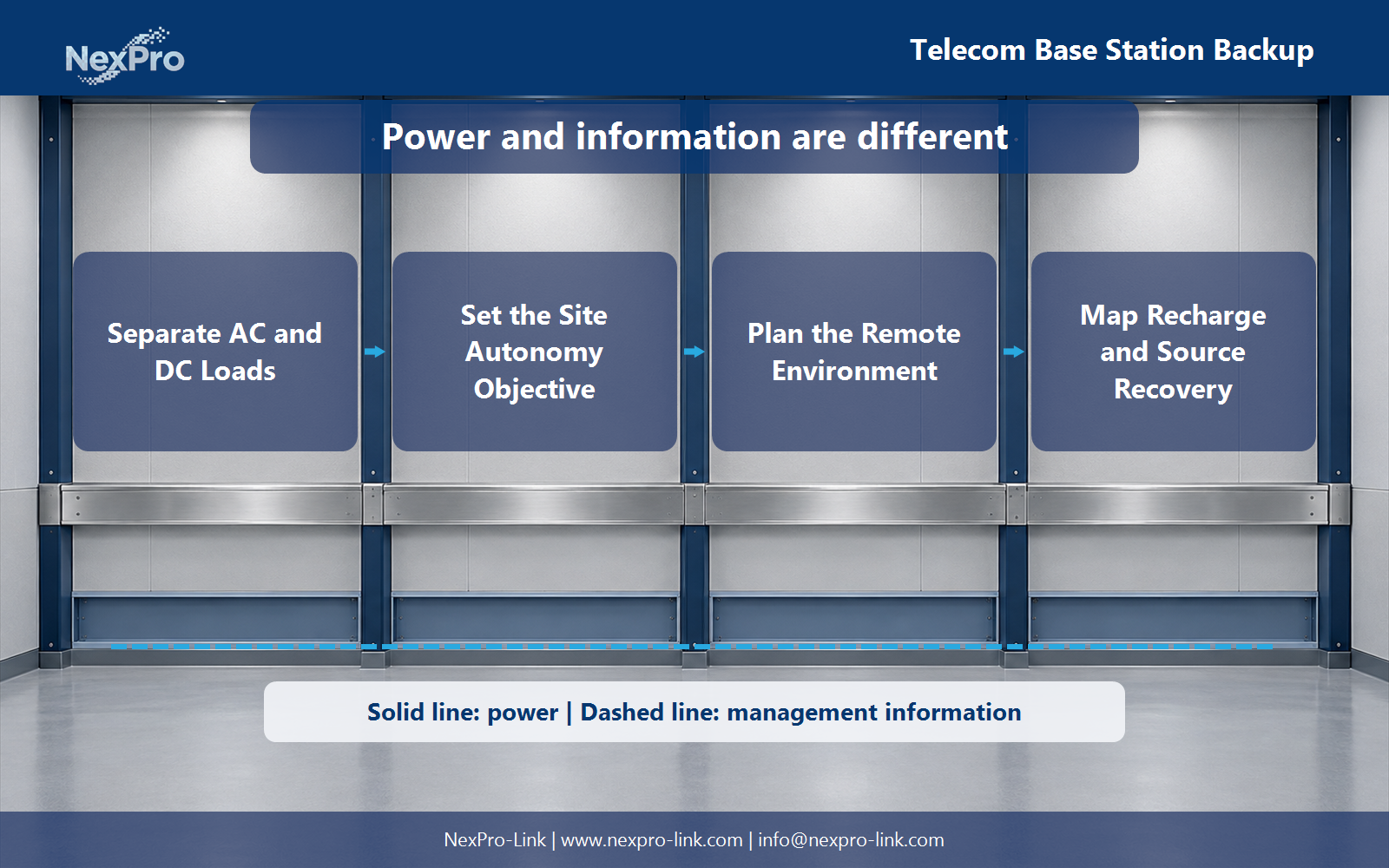
Power delivery and management information are different paths. The power drawing should show the selected source, backup boundary and included load. The monitoring drawing should show the interface, protected communication device and recipient path. This is a functional project map, not a claim that every device supports the same protocol or remote action.
Section 06
Keep an AC auxiliary calculation separate from the DC plant
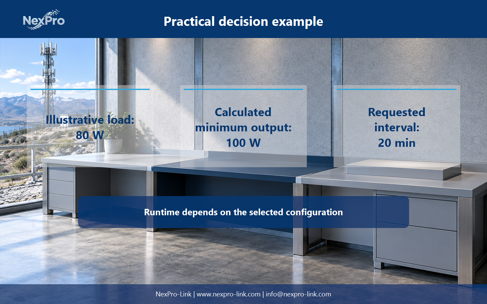
Consider an illustrative AC auxiliary load with an edge computer at 45 W, a router at 15 W and a switch at 20 W. The AC boundary totals 80 W. With a teaching power-factor assumption of 0.90, the apparent-power estimate is about 89 VA. A stated 80% utilization ceiling would produce a minimum 100 W and 111 VA planning check.
For a 20-minute objective, the load-side energy is about 26.7 Wh. That value describes energy delivered to the 80 W load. It does not specify a battery pack or promise runtime because conversion losses, battery condition, temperature and the selected UPS configuration remain outside this teaching calculation.
| Field | Teaching value | Use |
|---|---|---|
| Protected AC load | 80 W | Separate from the DC telecom service schedule |
| Apparent-power estimate | 80 W / 0.90 = 88.89 VA | Check against the AC UPS VA rating |
| 80% utilization check | 100 W and 111.11 VA minimum | Planning threshold, not a product recommendation |
| 20-minute load energy | 26.67 Wh | Load-side energy only |
Section 07
Prepare a mixed-power brief for procurement
Send the AC schedule, DC schedule, autonomy objective, enclosure conditions, source-recovery assumptions and remote-alarm requirements as separate fields. The brief should make clear which UPS equipment, distribution items and monitoring interfaces are in the requested supply scope, and which specialist telecom design tasks remain with the responsible project teams.
Share the AC and DC load schedule, site autonomy target and environmental limits with NexPro-Link to discuss UPS equipment, interfaces and supply scope for the project. A DC plant, rectifier or telecom approval should only be included where the project documents specifically define it.
Section 08
FAQ: telecom AC and DC backup planning
Does a base station need one UPS for every device? Classify devices by their actual input interface first. DC telecom loads may belong to the DC plant, while AC auxiliary loads need their own backup boundary.
How long should the site remain operational? Set that objective from the retained service, outage exposure and available recovery arrangements. Nominal battery capacity alone cannot answer it.
What matters beyond electrical capacity at a remote site? Record enclosure environment, heat removal, access route and communication availability with the load and autonomy data.
Which alarms should reach the network team? Prioritize source loss, battery operation, low reserve and equipment trouble, then confirm that the reporting path stays powered during the event.
Engineering references
These sources support the general planning principles. Always use the selected product's current datasheet and applicable project standards for final design.