Find the shared power and network dependencies first, then decide the tiered supply and recovery order. Plan the project from a system dependency sketch and the essential services to keep available.
Section 01
Find the shared dependencies first
Why can one rack outage affect several building systems? Different applications may share a switch, server, controller or power distribution point. Losing that dependency can interrupt several services even when their local devices remain powered. Build a dependency graph instead of assuming every building system fails together; dedicated life-safety systems require their own approved power arrangements. Property management, main contractors and ELV / weak-current engineers can use that boundary to build the dependency graph: service / shared node / supply / local fallback and prepare a system dependency sketch and the essential services to keep available before selection.
Find the shared power and network dependencies first, then decide the tiered supply and recovery order.
Create a service-to-node map before adding backup time. For each service, name the shared server, switch, controller and supply point, then record what still works locally when the shared node is unavailable. This exposes small components with a large operational effect.
| Service | Shared node | Local fallback |
|---|---|---|
| Access management | Core rack switch and access server | Controller cache without central management |
| CCTV recording | Core switch, recorder and storage | Possible camera edge buffer |
| Visitor management | Application server and network | No central workflow |
Section 02
Separate essential and deferrable loads
The priority decision belongs to the operating plan, not the device label. A core switch may draw little power but support every essential service. A display may draw more while remaining deferrable. Classify loads by outage consequence, runtime objective and owner.
Keep life-safety and other specialist systems outside a general IT or ELV example unless the responsible design explicitly includes them. Their power and compliance basis may be different. The server-room package should state that boundary clearly.
- Essential loads continue or complete a controlled stop.
- Deferrable loads pause when the operating plan permits.
- Excluded systems remain under their responsible design and approval path.
Section 03
Trace power and communication as separate layers
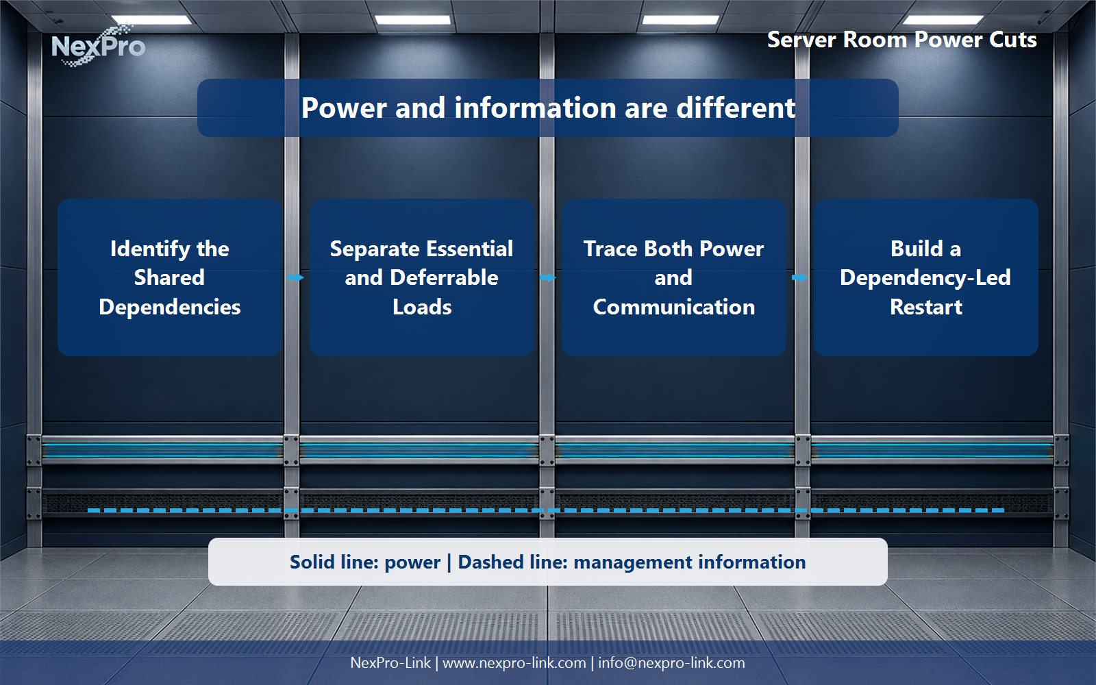
An electrical single-line shows energy flow, while the application map shows data, control, authentication and management. Keep these drawings separate and connect them by shared node names. A solid power route and a dashed communication route are easier to troubleshoot than one line that tries to mean both.
The management path matters during shutdown and restart. If the switch carrying the UPS command or storage status drops first, the remaining battery time cannot be used as planned. Keep that network segment inside the protected boundary until the sequence is complete.
| Layer | Carries | Example |
|---|---|---|
| Power | Electrical energy | UPS output to rack PDU, switch and hosts |
| Communication | Data and management | Uplink, storage path and controller heartbeat |
| Shared nodes | Both responsibilities | Core switch, management server and storage controller |
Section 04
Build a dependency-led restart
Restore prerequisites before dependent services. Confirm stable UPS output and network links, then bring storage and servers online, then controllers and client stations. Each stage needs an observable confirmation before the next group starts.
The exact order follows the installed system and safety plan. A short written runbook should name the prerequisite, action, verification and dependent service. It should also explain what to do when one stage fails rather than asking operators to continue blindly.
Section 05
Size the package from service groups and rehearse it
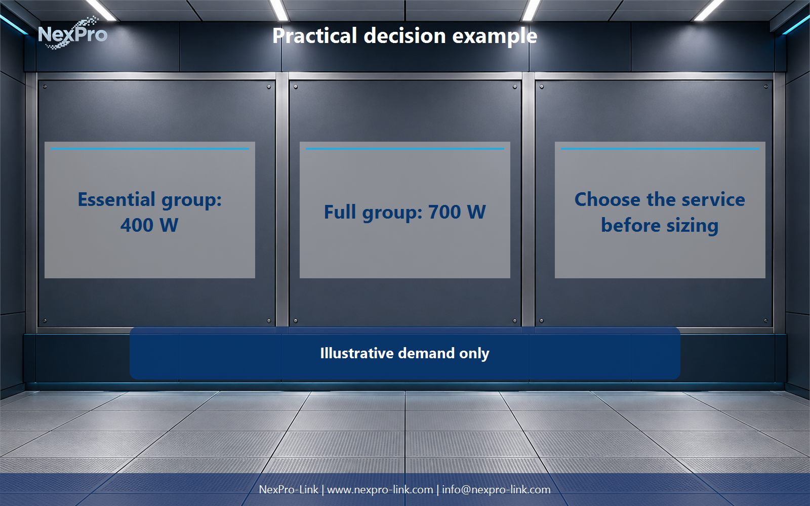
In the teaching example, essential application, recording and network equipment totals 400 W. Adding optional displays and auxiliaries raises the group to 700 W. The UPS is sized from the service the site chooses to maintain, not from the room label.
Test the runbook first as a tabletop exercise, then verify notifications and individual dependencies in an authorized window. Any live interruption needs defined boundaries, observers, a stop condition and a restoration check. The purpose is to learn without creating a second outage.
Section 06
FAQ: server-room dependency and recovery planning
Why can one rack outage stop several systems? They share network, application, storage or distribution nodes that are easy to miss when each system is drawn alone.
Should all ELV equipment have the same backup priority? No. Priority follows operational consequence and the agreed runtime objective.
Is an electrical single-line enough? No. Add a communication and application layer so shared services and management paths remain visible.
What should restart first? Restore and verify prerequisites before the services that depend on them. The installed architecture determines the final order.
Engineering references
These sources support the general planning principles. Always use the selected product's current datasheet and applicable project standards for final design.