Release each public-route cluster against its accepted sightlines, routed links and local power, not the number of villas completed. Mark private terrace or doorway exposure as a separate view-review issue.
Section 01
Approve shared public observation zones
Release each public-route cluster against its accepted sightlines, routed links and local power, not the number of villas completed. Mark private terrace or doorway exposure as a separate view-review issue. If one cluster lacks its node, keep its operational status open without withholding independently completed clusters or counting delivered cameras as coverage.
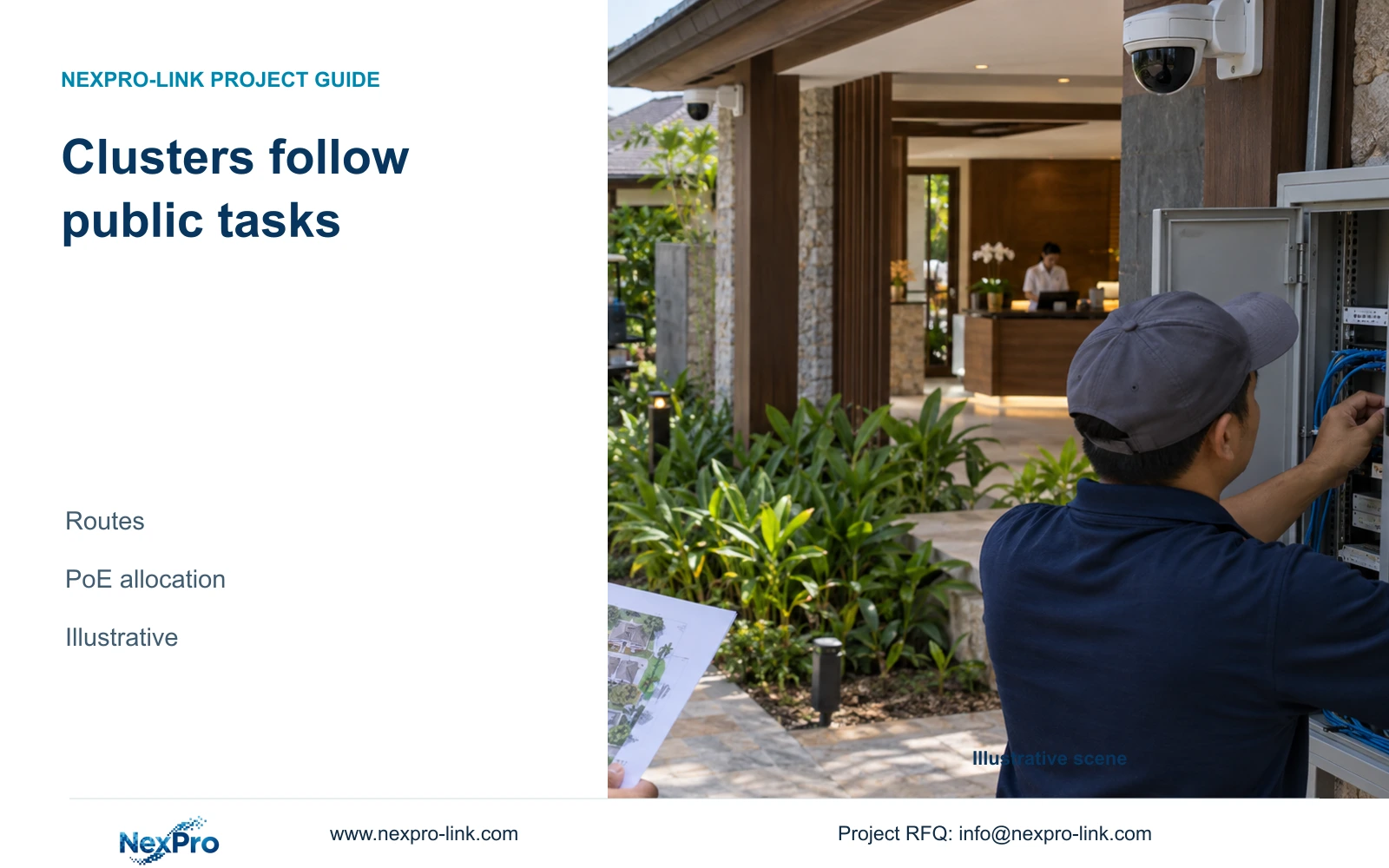
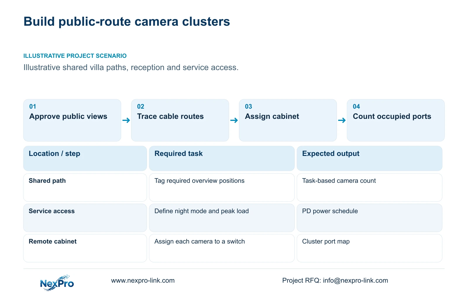
Group cameras by approved public observation tasks and the infrastructure that can serve them. Use this approach when villas share routes, reception facilities or service access. Change a cluster when its permitted view, installed cable route or supplying cabinet changes. Private living spaces are excluded from default coverage.
Start with entrances to shared facilities, public circulation junctions and authorized service handover points. State what each view must show and identify unnecessary private space at its edges. A position beside a villa may serve a shared path without justifying a view into its interior or private terrace.
Lighting and the chosen observation task also affect equipment demand. A camera expected to use illumination at night needs a peak-power input for that operating mode. The supplied camera PDFs do not provide maximum watts, so a planning power figure must remain labeled as an assumption until the exact equipment requirement is available.
| Required task | Given information | Decision still needed |
|---|---|---|
| Observe shared route | Public path on layout | Permitted view and target detail |
| Observe service handover | Service access location | Night mode and camera peak power |
| Maintain recording | Remote cabinet proposed | Local power and outage boundary |
Section 02
Map cabinet service areas using installed routes
Draw the actual cable routes from each proposed camera to its supplying cabinet. Include vertical sections, detours and termination allowances. A circle around a cabinet on a site plan is useful for orientation, but straight-line distance cannot establish the installed link length.
Compare an existing cabinet with a new remote node using the same required views. The remote node can shorten camera tails, while adding local power, environmental protection and maintenance responsibilities. Assign each camera to one documented supplying switch so its power demand cannot disappear into a hotel-wide average.
The Fluke Networks source describes the typical 90 m permanent-link and 100 m channel distinction. Apply the project's specified test basis and cable category. SP5648 is a Cat6 48-port patch panel and DT968MX is a Cat6 module; neither identifies a cable reel or proves the complete installed link's performance.
| Item | Existing cabinet | New remote cabinet | Effect |
|---|---|---|---|
| Camera tails | Longer route possible | Shorter local routes | Check each permanent link |
| Power | Existing boundary to verify | New local supply required | Include outage protection |
| Service | Established access route | Additional visit location | Price access and responsibility |
Section 03
Count positions from observation tasks
Give each proposed position a camera tag and a task. Separate an overview of a route from a detail view at a handover point where both are required. Combine views only when the approved tasks remain visible under the relevant layout and lighting conditions.
The illustrative CASE04 resort has 96 cameras across three recording groups. Its 240-room background does not calculate that camera count. Its six access nodes each serve 16 cameras. The eight-camera power example below is an independent cluster exercise, so its output budget must not be copied into those 16-camera nodes.
For an eight-camera cluster, define eight occupied access ports before adding any spare-port requirement. Independently collect the powered-device peak watts and required PoE type for every camera. A spare port is usable for expansion only when the switch also has sufficient per-port capability, total power and an appropriate data path.
Section 04
Calculate PoE demand at each supplying switch
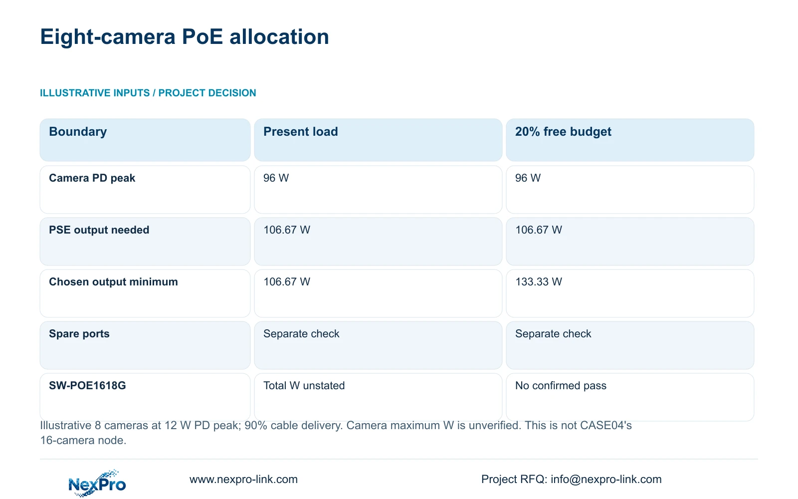
Assume eight cameras at a hypothetical 12 W peak each and 90% cable delivery efficiency. The powered-device, or PD, group demand is 8 × 12 = 96 W. Required power-sourcing equipment, or PSE, output is 96 / 0.90 = 106.67 W.
If the project requires 20% of the usable output budget to remain free, divide by 0.80: 106.67 / 0.80 = 133.33 W. This reserve convention is a stated project assumption. It does not define a universal PoE rule or include a spare-port count.
NexPro SW-POE1618G has 16 PoE access ports and two uplinks in its source record, with af/at descriptions. Its total PoE wattage is not stated, and the Gigabit title conflicts with the detailed 10/100 Mbps access-port description. Keep it as an inquiry candidate until the supplier responds to the required output budget, port capability and speed. Neither option in the table proves this candidate passes.
| Metric / condition | Present-load output | Budget retaining 20% free |
|---|---|---|
| PD group peak | 96 W | 96 W |
| Required PSE output | 106.67 W | 106.67 W |
| Minimum chosen output budget | 106.67 W | 133.33 W |
| Free port requirement | Check separately | Check separately |
| SW-POE1618G total power | Not stated in source | Must not assume it passes |
Section 05
Compare backbone options with their power scope
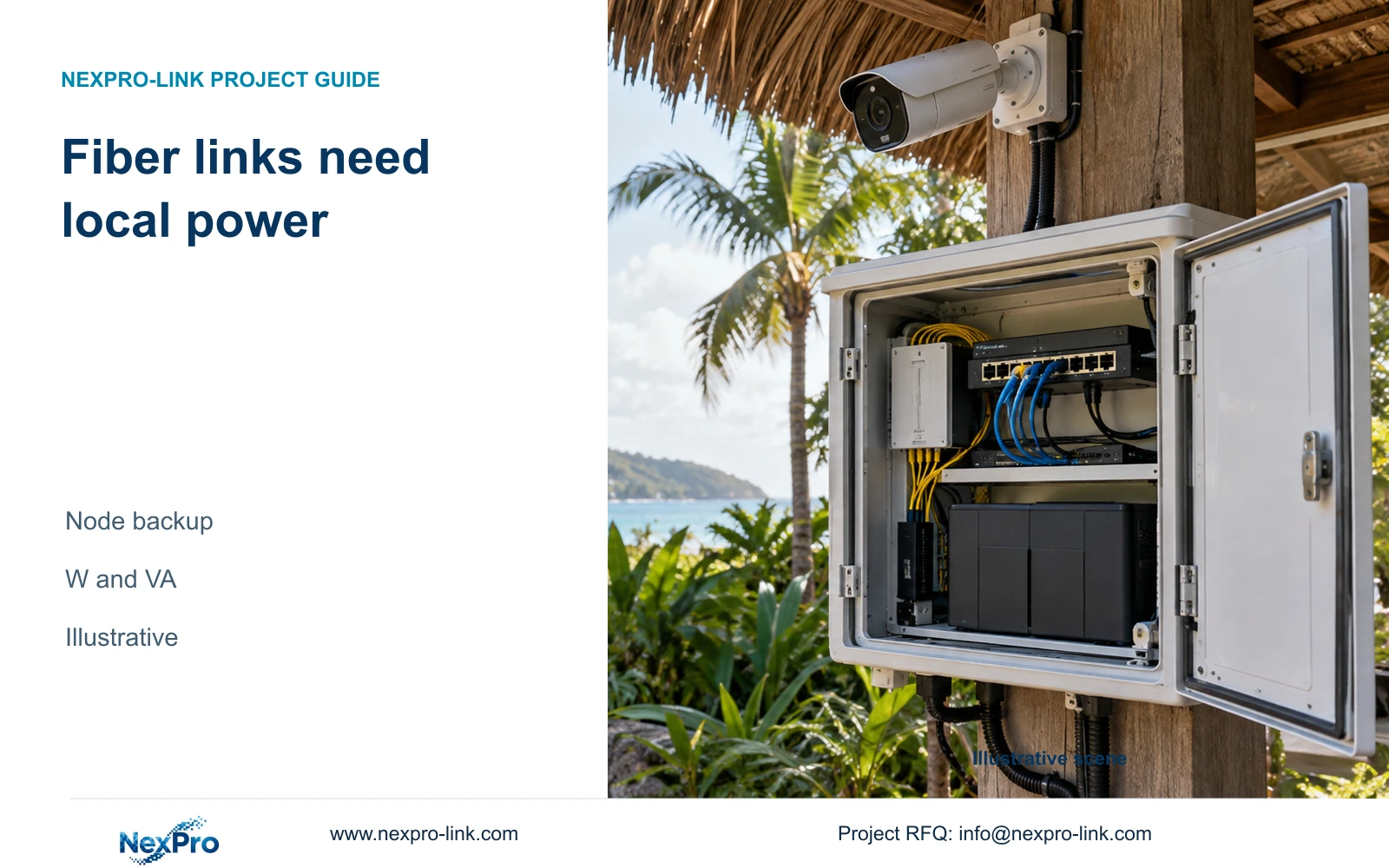
Compare direct copper, a relocated service cabinet and a fibre-fed remote node using the same camera tasks. Include route construction, active equipment and local power in the evaluated scope. Fibre may suit an interbuilding data route, but it does not automatically power the remote switch or cameras.
Cascaded devices or extension arrangements introduce additional dependencies. Identify which camera group loses service when an intermediate node fails, who can reach that node, and which links carry recording and viewing traffic. A lower accessory price can represent a larger restoration task if these responsibilities are omitted.
For UPS planning, use the complete measured switch AC input or a clearly bounded estimate. Complete switch input already includes its downstream PoE load; do not add those cameras again. Select the backbone arrangement that preserves the required recording state and remains serviceable, then price its full installation and support scope.
Section 06
Release equipment by confirmed cluster
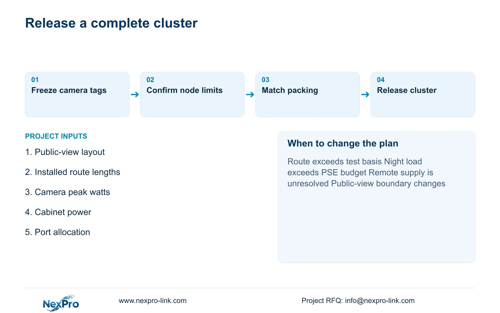
Prepare a cluster release containing camera tags, supplying ports, continuous cable routes and the minimum PSE output budget. Keep actual product specifications beside the engineering requirements. An unresolved total-watt field should remain an open selection item rather than becoming an assumed pass on the purchase order.
Release a ready cluster when its interfaces and site responsibilities are settled. Hold a cluster whose camera route, night-power requirement or cabinet supply remains unresolved, without changing the approved observation tasks elsewhere. If project packing is requested, map boxes and labels to the cluster schedule while preserving model and serial traceability.
Recommend infrastructure-based grouping where approved public tasks can be served within the selected route, port and power limits. Split or relocate the cluster when any limit fails. Send an annotated public-area layout, cabinet locations, installed route lengths and available camera peak-power data to info@nexpro-link.com. NexPro-Link can discuss a matched BOM and coordinated supply scope, with CCTV manufacture and supporting equipment responsibilities identified separately.
Section 07
Buyer questions
Can every villa receive the same camera kit? Only where the approved public tasks and infrastructure requirements genuinely match. Shared-path geometry, obstructions and cabinet routes can require different quantities even for identical villa buildings.
Does a 16-port switch provide enough expansion capacity? Port count establishes only one resource. Request the usable total PoE budget, required per-port capability and uplink specification, then allocate spare ports and spare power independently.
Can a preliminary quotation start without final drawings? Yes. Mark provisional clusters and unresolved routes explicitly, provide the project stage and destination, and distinguish the budget proposal from a confirmed equipment release.
Engineering references
These sources support the general planning principles. Always use the selected product's current datasheet and applicable project standards for final design.