Why does the installation location matter? Onboard equipment, trackside communication and ordinary station-room IT can fall under different requirements. Define the equipment role and environment first.
Section 01
Define the Installation Location
Why does the installation location matter? Onboard equipment, trackside communication and ordinary station-room IT can fall under different requirements. Define the equipment role and environment first. The word railway does not identify one universal UPS configuration or one complete approval package. This guide turns that point into a practical project decision, with a worked scenario and the inputs needed for a defined equipment proposal.
Onboard equipment, trackside communication and ordinary station-room IT can fall under different requirements. Define the equipment role and environment first. The word railway does not identify one universal UPS configuration or one complete approval package.
Capture the answer in the location map: station room / trackside / onboard / role before equipment is compared. This gives the project team a concrete service target and exposes missing dependencies early.
| Decision area | Project question | Required output |
|---|---|---|
| Define the Installation Location | Why does the installation location matter? | Location map: station room / trackside / onboard / role |
| Separate Safety-Critical Functions | Can a general communication UPS package cover all railway control functions? | Scope table: function / safety role / specified supply / owner |
| Understand EMC Applicability | Is EN 50121 a single all-purpose railway certificate? | Requirement map: application / part / equipment boundary / purpose |
Section 02
Separate Safety-Critical Functions
No. General IT and communication support must be distinguished from safety-critical signalling or protection functions. For a project-specific decision, record function, safety role, specified supply and owner in the scope table. This keeps the equipment inputs and intended service outcome aligned.
Use the scope table: function / safety role / specified supply / owner to keep real interfaces and operating states visible. Measured demand, equipment limits and future allowances should remain separate entries.
Section 03
Understand EMC Applicability
It is a series with application-specific parts. Identify the relevant part and equipment boundary rather than using the series name as a blanket product endorsement. EMC requirements do not by themselves establish all electrical, functional or operational suitability.
Review the requirement map: application / part / equipment boundary / purpose with the owners of the connected systems. Power continuity only supports the functions that remain connected and available during the event.
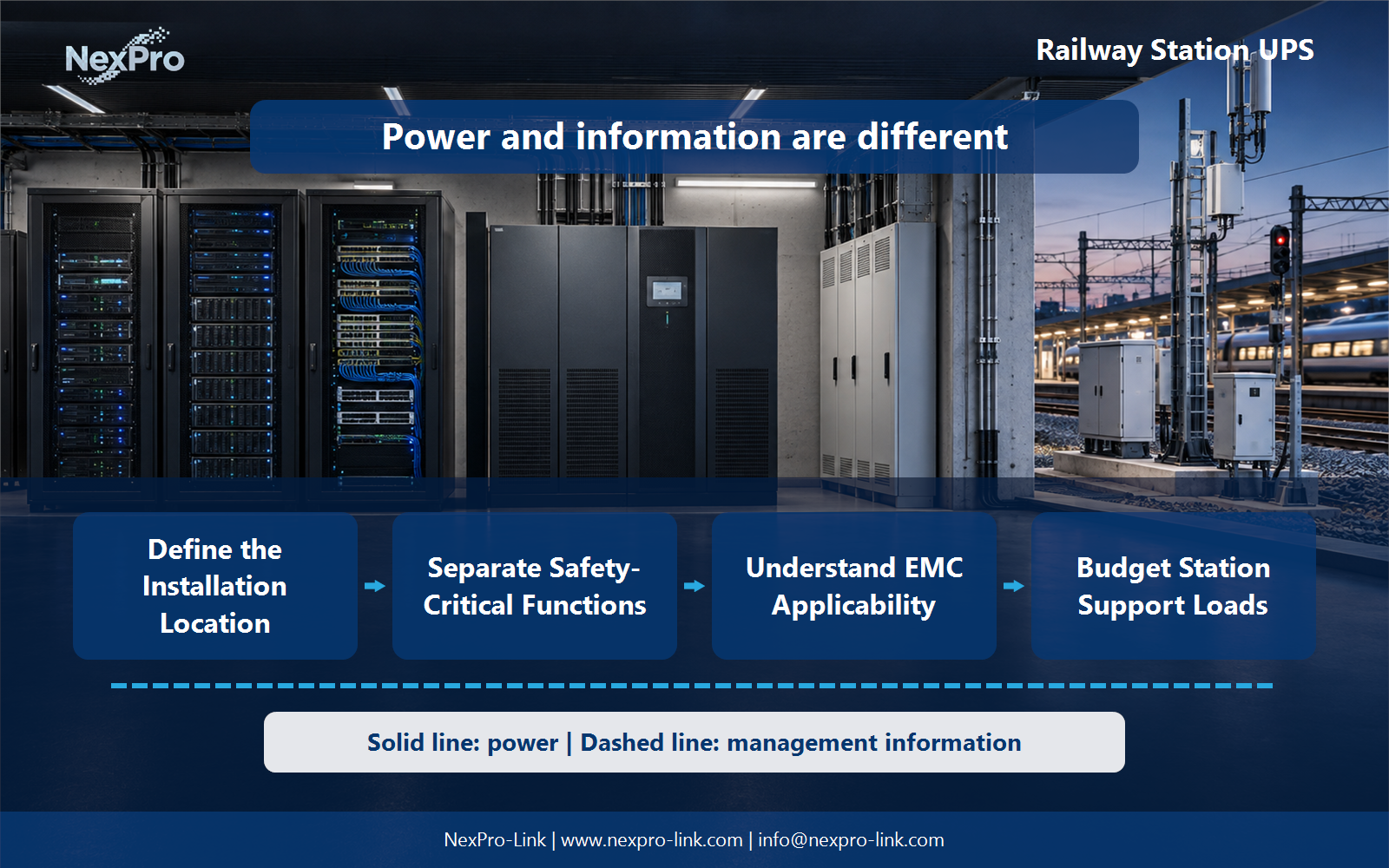
- Confirm the answer to: Is EN 50121 a single all-purpose railway certificate?
- Draw electrical power as a solid path and management information as a separate dashed path.
- Keep external services and specialist approvals outside the UPS equipment claim.
Section 04
Budget Station Support Loads
Include the designated networking, servers and operator equipment, with their actual input and failure-state demand. Keep other railway systems separately identified. Use the required service duration instead of assuming that every station follows one backup interval.
Document this choice in the load schedule: support device / w-va / feed / service interval, including the condition that triggers it and the person responsible for the response.
Section 05
Plan Maintainable Deployment
Consider permitted access periods, replacement routes, environmental constraints and operational coordination. Define whether work can occur with the protected service stopped or needs an approved alternative path. Do not assume hot replacement is available for any battery or UPS.
Test the sequence represented by the service map: access / isolation objective / alternative / replacement during an approved maintenance window. Record the observations needed to confirm recovery.
Section 06
Prepare the Railway-Support Brief
Provide the installation role, power schedule and exact project requirements. NexPro-Link can discuss equipment and supply options within that scope. Any railway qualification should be tied to the actual configuration and application rather than a general marketing label.
Send the completed brief: location / load / applicable requirement / interfaces / service with the project request. It is more useful than a capacity number without interfaces, operating states or a defined service boundary.
Engineering references
These sources support the general planning principles. Always use the selected product's current datasheet and applicable project standards for final design.