Discuss only the power dependencies of approved ATS support equipment, without defining train-control safety logic. Plan the project from the approved ATS support-equipment scope, power paths and system recovery.
Section 01
Define the Approved Support Scope
Discuss only the power dependencies of approved ATS support equipment, without defining train-control safety logic.
Focus on the defined support servers, networks and operator interfaces in the approved project scope. Train-control safety functions require their own system requirements. For a project-specific decision, record server, network, workstation and excluded safety function in the scope map. This keeps the equipment inputs and intended service outcome aligned.
Capture the answer in the scope map: server / network / workstation / excluded safety function before equipment is compared. This gives the project team a concrete service target and exposes missing dependencies early.
| Decision area | Project question | Required output |
|---|---|---|
| Define the Approved Support Scope | Which ATS-related equipment can be discussed generically? | Scope map: server / network / workstation / excluded safety function |
| Trace Operator Visibility | Why protect more than operator workstations? | Visibility chain: source / server / network / operator |
| Compare Failure-State Paths | How should redundancy be described? | State matrix: event / surviving path / retained function / common point |
Section 02
Trace Operator Visibility
A workstation depends on data sources, servers and communication paths. Trace those dependencies and their supplies. Keeping displays illuminated does not prove that operators have current or usable information, especially when a shared upstream component has stopped.
Use the visibility chain: source / server / network / operator to keep real interfaces and operating states visible. Measured demand, equipment limits and future allowances should remain separate entries.
Section 03
Compare Failure-State Paths
State the required failure or maintenance condition and show which equipment remains supported. Mark shared sources and distribution points. Do not assign N+1 or 2N merely from the ATS name or infer system safety from the number of UPS units.
Review the state matrix: event / surviving path / retained function / common point with the owners of the connected systems. Power continuity only supports the functions that remain connected and available during the event.
- Confirm the answer to: How should redundancy be described?
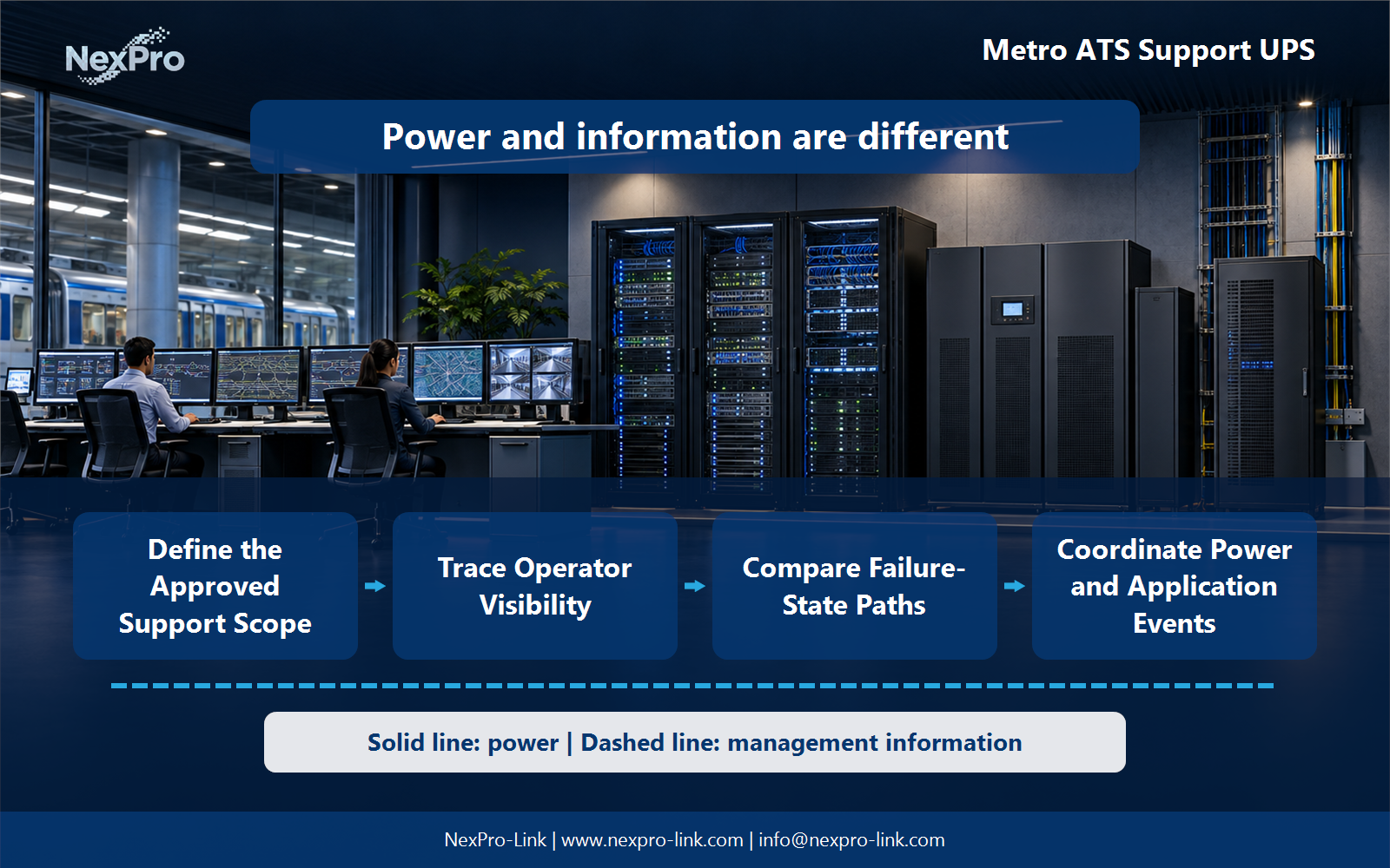
- Draw electrical power as a solid path and management information as a separate dashed path.
- Keep external services and specialist approvals outside the UPS equipment claim.
Section 04
Coordinate Power and Application Events
Only through supported, authorized integration and the system's approved operating procedure. Define the signal interface and responsibility. Avoid generic scripts that perform operational actions on a live railway system without the responsible system team's control.
Document this choice in the interface table: event / recipient / permitted response / owner, including the condition that triggers it and the person responsible for the response.
Section 05
Plan Recovery Confirmation
Confirm its dependencies, current data and operator access according to the platform's procedures. Electrical restoration is necessary but not sufficient. The responsible operations team determines readiness, not an automatic interpretation of a UPS normal-status message.
Test the sequence represented by the readiness map: supply / network / application / data / operations during an approved maintenance window. Record the observations needed to confirm recovery.
Section 06
Write the Supply Boundary
Send the approved equipment boundary, loads, feeds and required interfaces. NexPro-Link can discuss UPS supply against that specification. Functional-safety approval, railway qualification and operational acceptance remain explicit project responsibilities rather than implied capabilities.
Send the completed brief: approved devices / demand / feeds / integration / exclusions with the project request. It is more useful than a capacity number without interfaces, operating states or a defined service boundary.
Engineering references
These sources support the general planning principles. Always use the selected product's current datasheet and applicable project standards for final design.