Separate control and tracking loads from conveyor motor loads before sizing the UPS. Plan the project from sorting-line control loads, motor boundaries and safe-stop requirements.
Section 01
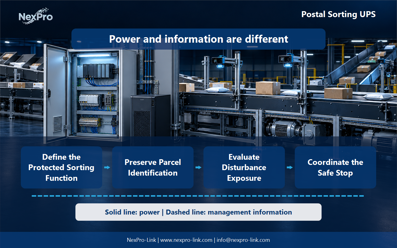
Define the Protected Sorting Function
Separate control and tracking loads from conveyor motor loads before sizing the UPS.
Not by default. Separate control, scanning and tracking equipment from conveyor drives and motors. The process owner should define the required safe state and restart behavior. A controls UPS does not automatically keep mechanical transport operating safely.
Capture the answer in the boundary table: plc / scanner / tracking / drive / motor before equipment is compared. This gives the project team a concrete service target and exposes missing dependencies early.
| Decision area | Project question | Required output |
|---|---|---|
| Define the Protected Sorting Function | Should the UPS power the entire conveyor line? | Boundary table: PLC / scanner / tracking / drive / motor |
| Preserve Parcel Identification | Why protect identification and tracking equipment together? | Data chain: scan / controller / buffer / database / acknowledgement |
| Evaluate Disturbance Exposure | How should motor-related supply disturbances be handled? | Condition table: event / affected supply / load tolerance / option |

Section 02
Preserve Parcel Identification
A parcel can lose its useful tracking context if scanners, controllers or the local database stop at different times. Map their dependencies and buffering behavior. The objective is a recoverable parcel record, not merely longer runtime for one scanner.
Use the data chain: scan / controller / buffer / database / acknowledgement to keep real interfaces and operating states visible. Measured demand, equipment limits and future allowances should remain separate entries.
Section 03
Evaluate Disturbance Exposure
Characterize the relevant supply conditions and equipment tolerance through the responsible electrical team. Compare suitable UPS behavior at the protected load boundary. Do not declare transformer construction universally mandatory simply because conveyors are present nearby.
Review the condition table: event / affected supply / load tolerance / option with the owners of the connected systems. Power continuity only supports the functions that remain connected and available during the event.
- Confirm the answer to: How should motor-related supply disturbances be handled?
- Draw electrical power as a solid path and management information as a separate dashed path.
- Keep external services and specialist approvals outside the UPS equipment claim.
Section 04
Coordinate the Safe Stop
It should support the approved control and data-preservation sequence. Define event delays, controller behavior and operator indication. Avoid suggesting bypasses of interlocks or unsupervised live tests; the UPS is supporting equipment, not a substitute for the machine safety design.
Document this choice in the sequence map: event / control action / data action / safe state, including the condition that triggers it and the person responsible for the response.
Section 05
Plan Recovery and Reconciliation
Compare the last recorded parcel events with the actual process state before restarting the flow. Define who resolves uncertain positions and duplicate reads. Power restoration is only the first step in returning a sorting line to dependable operation.
Test the sequence represented by the recovery log: last event / physical state / discrepancy / owner during an approved maintenance window. Record the observations needed to confirm recovery.
Section 06
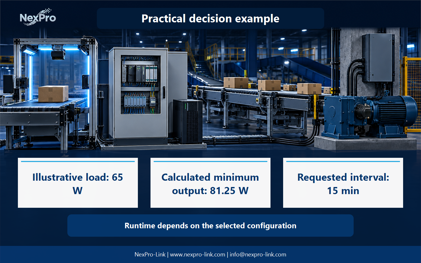
Build a Controls-Only Equipment Brief
Provide the protected controls and IT loads, input interfaces, cabinet conditions and approved outage behavior. NexPro-Link can discuss UPS equipment for this scope. Any requirement to support drives or whole machinery needs its own engineered specification.
Send the completed brief: control w / interface / environment / process boundary with the project request. It is more useful than a capacity number without interfaces, operating states or a defined service boundary.
Engineering references
These sources support the general planning principles. Always use the selected product's current datasheet and applicable project standards for final design.