An NVR UPS design must protect every powered dependency needed for recording. This guide separates load counting, W and VA capacity, and battery runtime.
Section 01
Define which recording services must survive
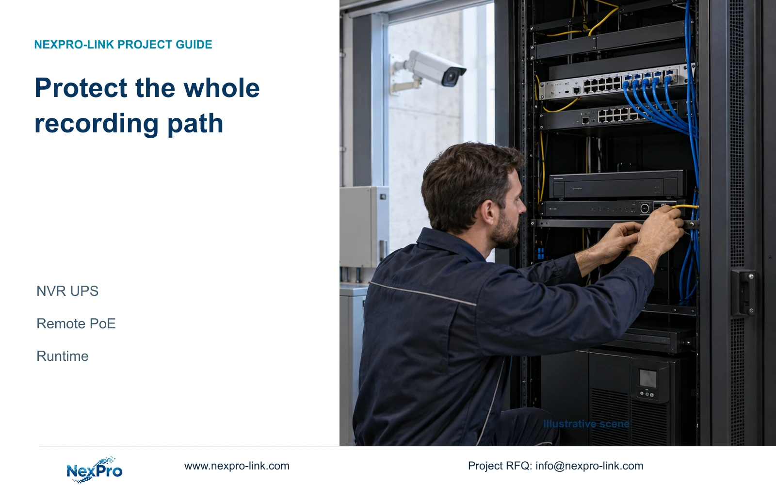
Backing up the recorder alone keeps recording available only while its cameras and required network equipment also remain powered. Build the UPS load from the complete recording path, including remote PoE access nodes, the necessary core switch and the NVR with its disks. Decide separately whether an operator display must remain available. Count each electrical load once, calculate both watts and volt-amperes, and check battery runtime against the selected configuration. In the illustrative calculation below, a 510 W protected load requires a planning rating of at least 637.5 W and approximately 708.33 VA, but those capacity figures do not establish a 30-minute runtime.
Write the outage objective before selecting equipment. Continuous recording, live observation and remote access have different dependencies. If the owner needs recording only, optional viewing equipment can have a different protection scope. If remote viewing is essential, identify the network devices required for that service instead of assuming the recorder's UPS covers them.
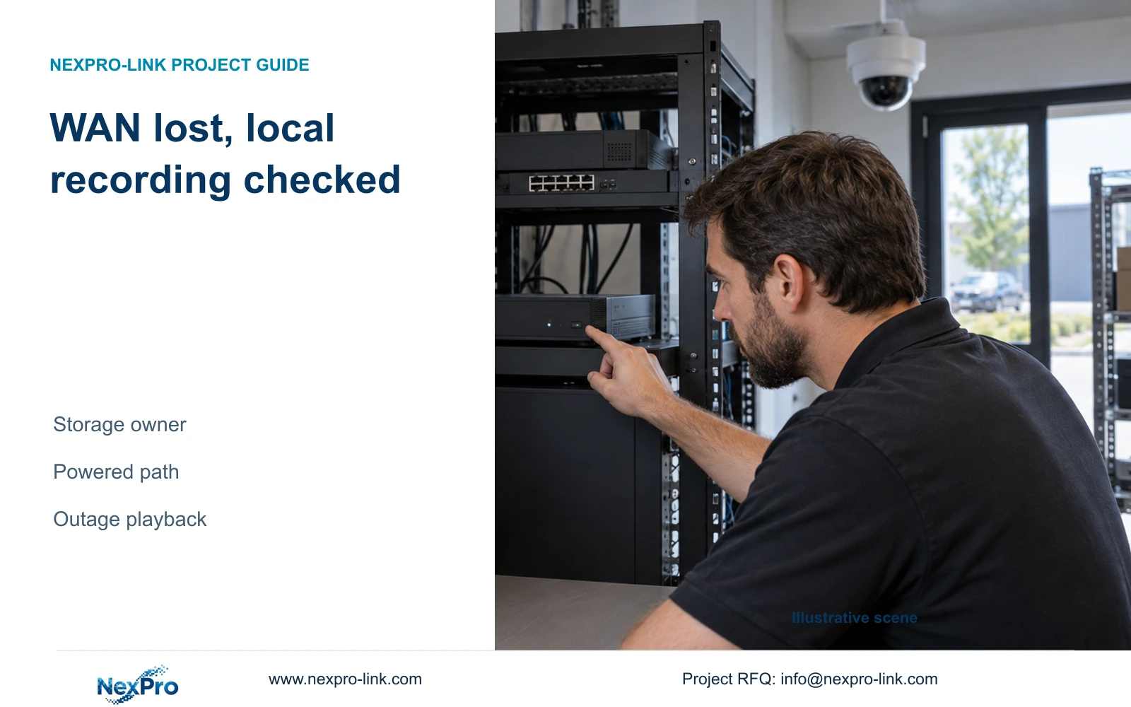
Also define the authorized response when the required service cannot continue. The supplied manual distinguishes logout, restart and shutdown. Logout ends an operator session; it does not stop the recorder. For a planned stop, preserve required exports, obtain authority and arrange the recording interruption. Use software shutdown before disconnecting power. Automatic restart does not establish uninterrupted recording.
Section 02
Trace camera power alongside the data path
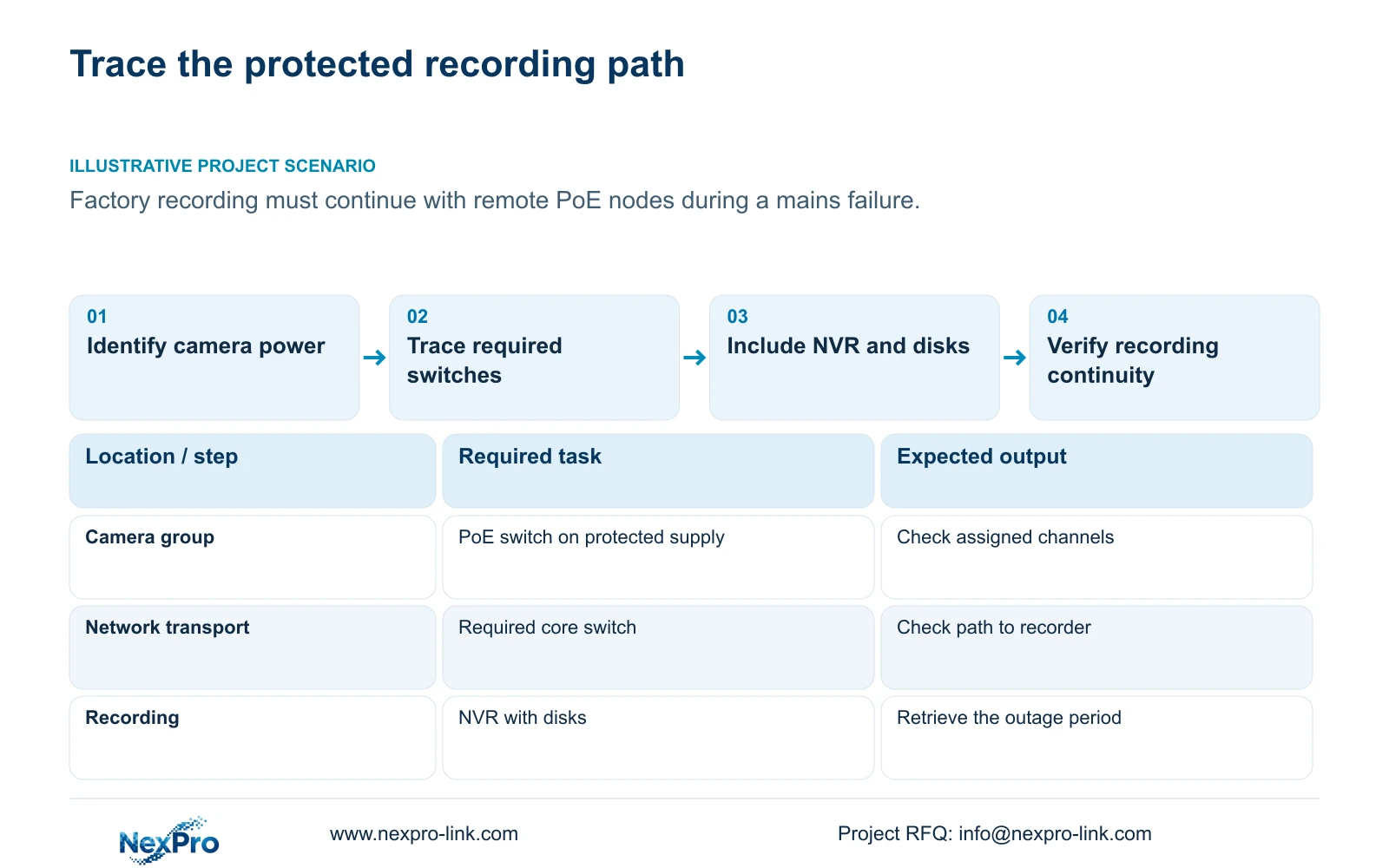
Draw camera-to-switch-to-recorder data connections and place the actual power source beside each device. The manual's non-PoE arrangement supplies the camera separately and connects the recorder through a switch. Its ordinary LAN socket is not shown supplying camera power. An external PoE arrangement needs a suitable power-sourcing device, with protection extending to its actual electrical feed.
Remote access switches deserve individual attention. A UPS beside the central recorder cannot protect a switch connected to an unprotected supply elsewhere in the factory. Identify which UPS or protected circuit serves each required node. Where a node has no protected source, recording from that camera group remains dependent on mains power.
Keep the display and mouse identifiable in the drawing without treating them as video transport equipment. Include the display's electrical demand only when it belongs to the agreed outage service. This makes the protection boundary readable to the equipment supplier and the party responsible for site power.
Section 03
Count PoE camera demand at the correct boundary
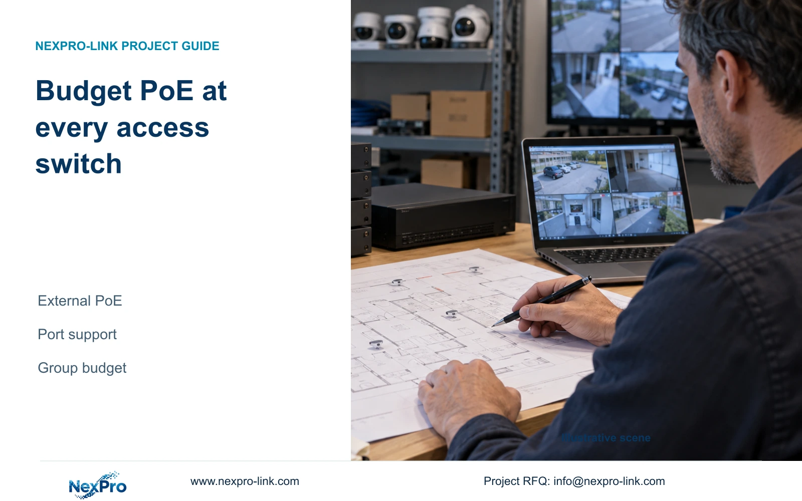
A PoE switch has two checks within its camera group: each port must support its assigned device, and the aggregate sourcing budget must support the group. Use actual maximum device requirements, cable assumptions and the chosen reserve. Having enough ports does not establish enough power, and a suitable link speed does not establish suitable power support.
For UPS sizing, determine what the switch's AC figure includes. A whole-switch AC input that already includes powered cameras must be counted once. Adding the same cameras again would inflate the protected load. Conversely, a chassis-only figure cannot represent the complete switch-and-camera group without further information.
If the available figure has an unclear boundary, retain it as unresolved. Obtain the complete input demand or an explicit calculation that includes the downstream load and relevant losses before using it in a UPS schedule.
Section 04
Calculate W, VA and load-side energy separately
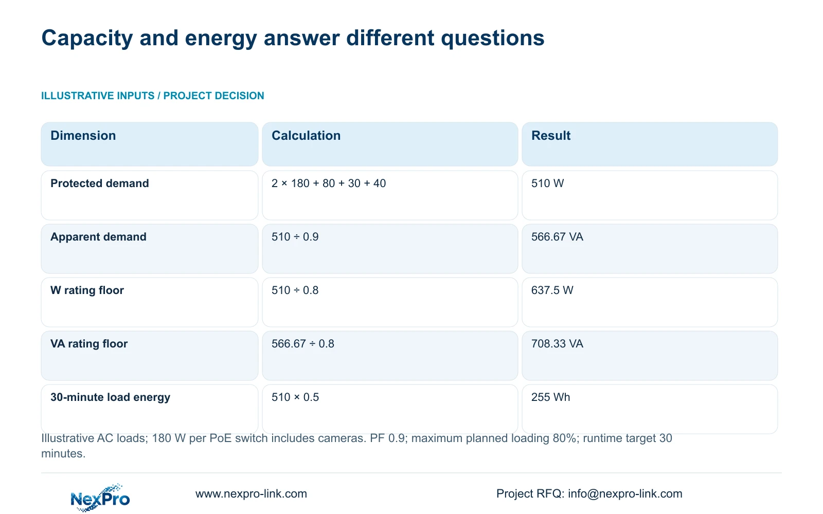
The teaching inputs are two PoE switches at 180 W each, with their cameras already included; an NVR with disks at 80 W; a core switch at 30 W; and an operator screen at 40 W. Total protected demand = 2 × 180 + 80 + 30 + 40 = 510 W. Assume aggregate power factor PF = 0.9 and a planning limit of 80% of the UPS rating.
Apparent demand = 510 W ÷ 0.9 ≈ 566.67 VA. The minimum planned watt rating = 510 W ÷ 0.8 = 637.5 W. The minimum planned VA rating = 566.67 VA ÷ 0.8 ≈ 708.33 VA. Both rating checks apply; passing one does not establish the other.
For a 30-minute target, time = 0.5 h and load-side energy = 510 W × 0.5 h = 255 Wh. This is the energy required by the loads over the assumed period. It is not a battery-nameplate selection or a runtime guarantee.
| Check | Calculated requirement | Next decision |
|---|---|---|
| W capacity | 637.5 W minimum planned rating | Compare with the candidate UPS watt rating |
| VA capacity | Approximately 708.33 VA | Check apparent-power capacity independently |
| 30-minute energy | 255 Wh at the load side | Verify battery configuration and runtime curve |
Section 05
Use the battery curve to qualify the candidate
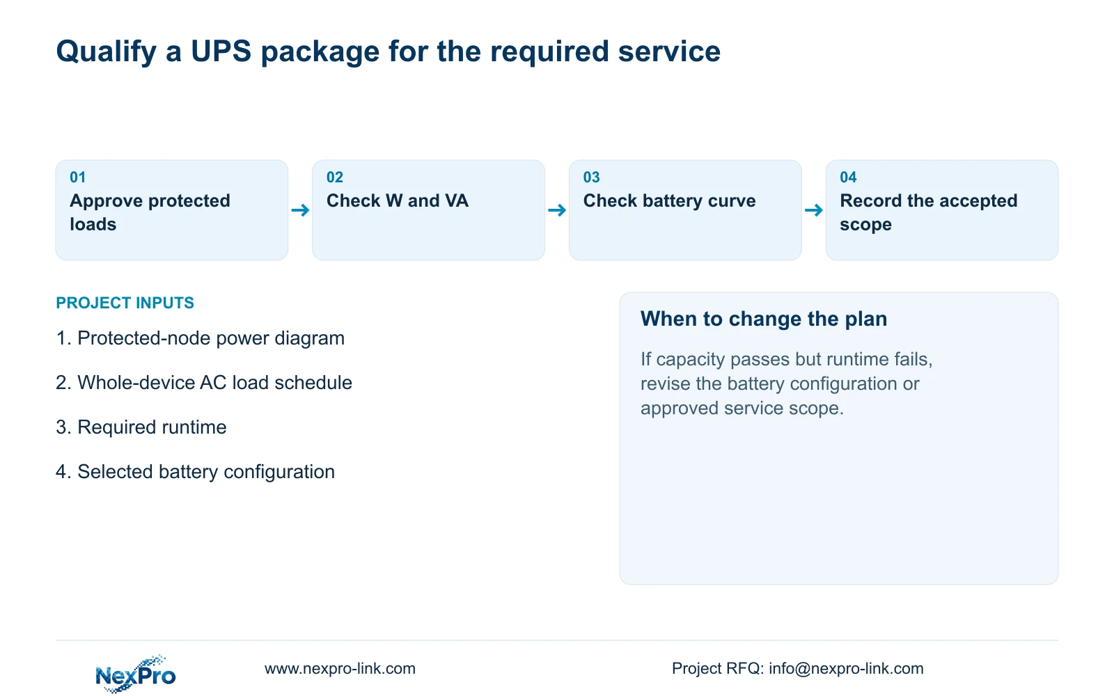
The public SP1KR(S) rating of 900 W / 1000 VA makes it a capacity candidate for these assumptions. The example does not establish that its battery configuration supports 30 minutes at 510 W. Confirm the actual battery arrangement, efficiency basis and applicable runtime curve for the intended load.
If runtime falls short while W and VA capacity pass, reconsider the battery configuration or the agreed protected service. Removing an optional display is a different decision from removing a required access switch. Record the consequence for the owner before revising the load schedule.
Keep recorder qualification intact during this review. Channel modes, incoming bitrate, playback combinations, usable storage and interfaces remain separate requirements. A larger UPS cannot correct a recorder capacity mismatch.
Section 06
Apply the calculation to remote factory nodes
Illustrative project scenario: A factory wants recording to continue during a short mains failure, including remote PoE nodes. The engineer marks every required camera group and its power source, then checks the switches' AC load boundaries. The owner decides whether the operator screen belongs to the protected service. Only after these choices does the team evaluate UPS capacity and the battery curve.
The resulting brief should identify the protected nodes, load basis, target runtime and site power boundary. NexPro-Link's BOQ and tender support can support that equipment-scope discussion; local electrical work and responsibility must remain explicitly assigned.
Section 07
Does 255 Wh mean a 255 Wh battery is enough?
No. It is the illustrative load-side energy requirement. Battery selection still needs the actual configuration, efficiency and runtime curve. The NVR manual provides no UPS runtime table.
Section 08
Prepare the protected-load schedule
Operating references are the supplied NVR4.0 user manual CH_V2.4.doc, §§3.1, 3.3.1, 4.1.4, 4.1.5 and 4.12.18, with recorder constraints in §§5.1 and 5.2. The filename says V2.4 and the body says V2.2; section references take priority. UPS sizing here is an engineering extension.
Send NexPro-Link the protected-load schedule and site power boundary, including the required runtime, at info@nexpro-link.com.
Engineering references
These sources support the general planning principles. Always use the selected product's current datasheet and applicable project standards for final design.