Shared hotel risers need one coordinated pathway allocation and separate system responsibilities. Cable quantities, cabinet space and maintenance access require different checks.
Section 01
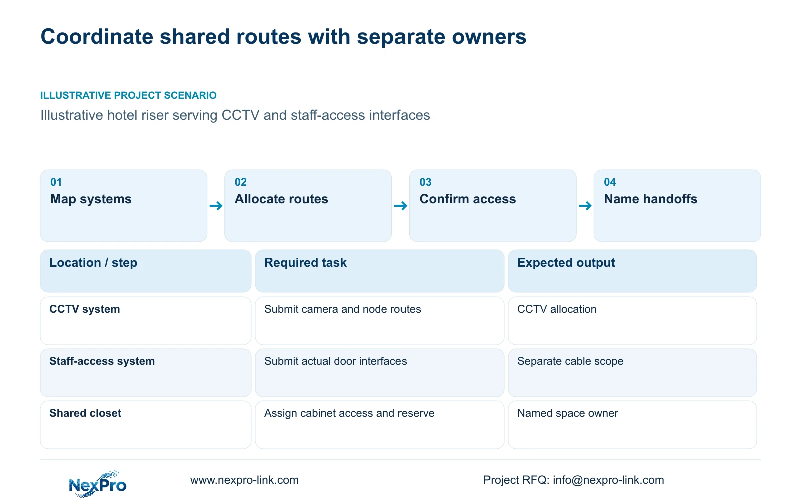
Assign a coordinator and identify participating systems
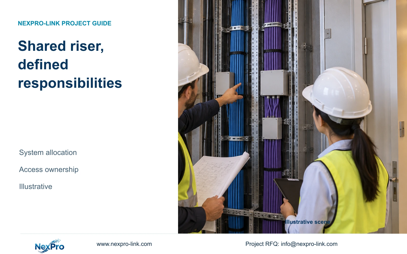
Use a consolidated pathway schedule for shared hotel risers, with a named coordination role and separate system installation responsibilities. Share the pathway only when the relevant project professionals confirm its capacity, access and construction conditions. Coordinated equipment supply does not transfer responsibility for building the riser or maintaining every system that uses it.
Identify which systems occupy each shaft and where their cables enter, leave and terminate. CCTV connections, staff-access equipment and hotel data services may have different endpoints and operating requirements. Record their actual participation in the project; do not infer a common cable or power arrangement because they appear in one procurement package.
Define the operating task behind each system’s allocation. For CCTV, required public views, recording and outage continuity determine which access nodes and backbones need space. For door systems, use the actual door and interface schedule. Optional display equipment should have a separate role, since a display is not inherently a necessary node in the recording path.
| Scope | System input | Coordination decision |
|---|---|---|
| CCTV pathway | Camera and access-node schedule | Assigned riser route |
| Staff-access pathway | Door and interface schedule | Separate system allocation |
| Shared closet | Equipment and service access | Named space and access owner |
Section 02
List cable quantities against actual riser sections
Each system should submit a route schedule that shows its cable identities, quantities and destination floors. Count what passes through each shared section, rather than applying the complete hotel cable total to every floor. A cable that leaves the riser at reception no longer occupies the upper-floor section.
For each shared shaft section, request the cable family, count and outside diameter, the proposed containment and reserved allocation, and the floor-entry/exit locations. Mark construction penetrations and name who obtains the project's approved support and firestopping details. Do not release pulling or closure while that interface is unassigned. The cabinet's U-space calculation below cannot answer these pathway questions.
Measure complete routes with horizontal approaches, shaft travel and termination allowances. Keep fixed copper and patch cords separate. The supplied Fluke Networks guidance uses typical 90 m permanent-link and 100 m channel bases, with the actual category and test arrangement determined by the project. A shared shaft can affect route length even when the same camera and closet remain selected.
State provisional routes and planned reserve separately from installed demand. Future space should have an intended use or explicit planning status. The complete illustrative hotel reference supplies a system context, but its cable quantity is not a universal riser allocation. Actual counts must follow the systems and routes that occupy the particular shaft.
Section 03
Coordinate access from the shaft to the equipment cabinet
Review how installers and maintenance staff reach the pathway and its termination points after finishes are complete. Identify the permitted access openings and any restricted work areas. The route should allow the agreed installation and service tasks without relying on an unspecified opening in decorative work.
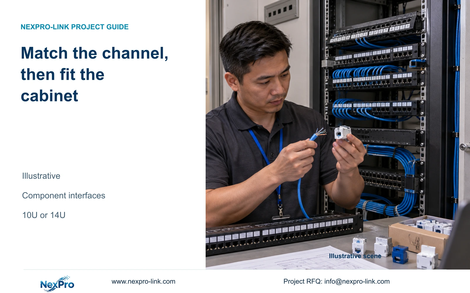
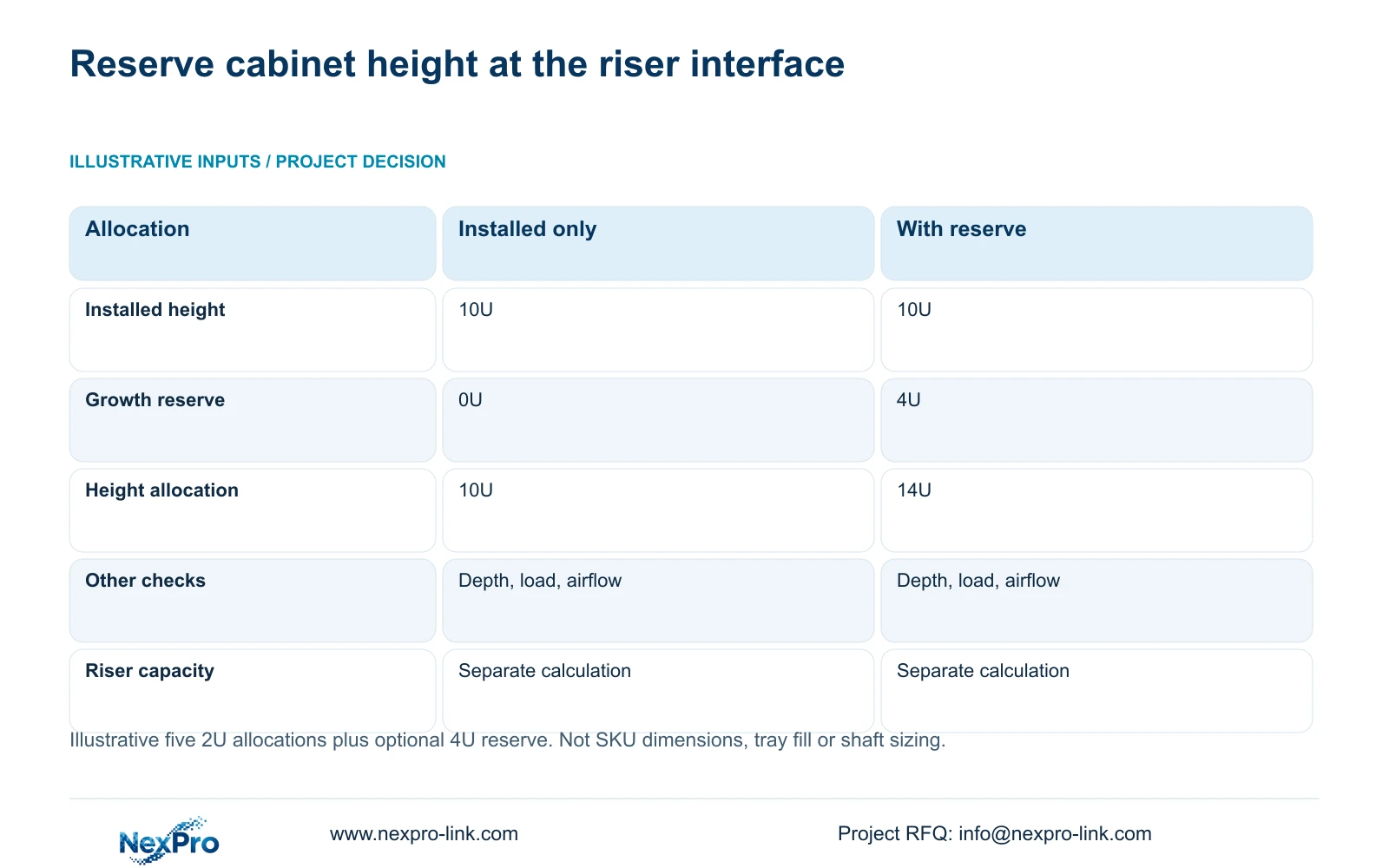
At the riser’s equipment interface, check the cabinet layout separately from pathway space. The illustrative height inputs allocate 2U each to patching, switches, recorder, UPS and cable management. Their sum is 10U. Adding a stated 4U reserve produces a 14U height allocation. These are planning allowances, not published dimensions of selected products.
Height does not establish cabinet suitability. Check actual device depth and weight, cable bends, front or rear service needs and airflow. UPS and battery mounting must meet the relevant supported arrangement and cabinet load conditions. Space in the shaft, cable-entry space and equipment rack height are different quantities and should remain in separate records.
Section 04
Compare dedicated and shared space with explicit reserves
A shared installation can use a coordinated cabinet or pathway, provided every system’s allocated space and maintenance responsibility remain identifiable. Dedicated allocation can be useful when independent access or service requirements make sharing impractical. Compare those conditions before deciding that unused common space is available to any contractor.
For the cabinet interface example, the installed-only option allocates 10U and no growth reserve. The alternative allocates the same installed 10U plus 4U, giving 14U. Choose the reserved allocation when the project accepts that growth allowance and the actual cabinet can accommodate it. This is not a tray-fill calculation and does not establish the required shaft dimensions.
Assign the reserve to a defined purpose or a controlled shared allowance. If another system uses it, update the remaining allocation and obtain the relevant project decision. Both cabinet options still need depth, load and airflow design. A larger nominal cabinet can remain unsuitable when equipment cannot be accessed or supported.
| Metric / condition | Installed equipment only | Installed plus planned reserve |
|---|---|---|
| Allocated installed height (U) | 10 | 10 |
| Reserved growth space (U) | 0 | 4 |
| Minimum height allocation (U) | 10 | 14 |
| Depth / load / airflow | Must still be designed | Must still be designed |
Section 05
Define cable labels and responsibility handoffs
Use a cable identity that connects the system, route and termination records. Label the installed endpoints consistently with the schedule, then associate test results and changes with that identity. A floor label alone is insufficient when several systems share the same shaft and terminate at different cabinets.
Distinguish equipment identity from location identity. SP5648 is a Cat6 48-port patch panel, and DT968MX is a Cat6 tool-free module. Preserve the real component model while recording the project cabinet and port assignment separately. These products do not define bulk cable specifications or prove the installed channel’s performance.
The handoff should state who supplies the component, installs the pathway, pulls and terminates cable, tests the link and maintains the equipment. Project packing or authorized OEM labels can help distribution by floor, but must preserve technical and traceability information. Choose installation-focused labeling when it serves the project; elaborate retail packaging has no necessary role in clarifying riser ownership.
| Outcome | Record | Responsible role to name |
|---|---|---|
| Usable pathway | Approved route and access arrangement | Pathway installer |
| Identified cable link | Endpoints and test record | System installer |
| Serviceable equipment | Model, port and access record | Maintenance owner |
Section 06
Freeze the installation interface before ordering
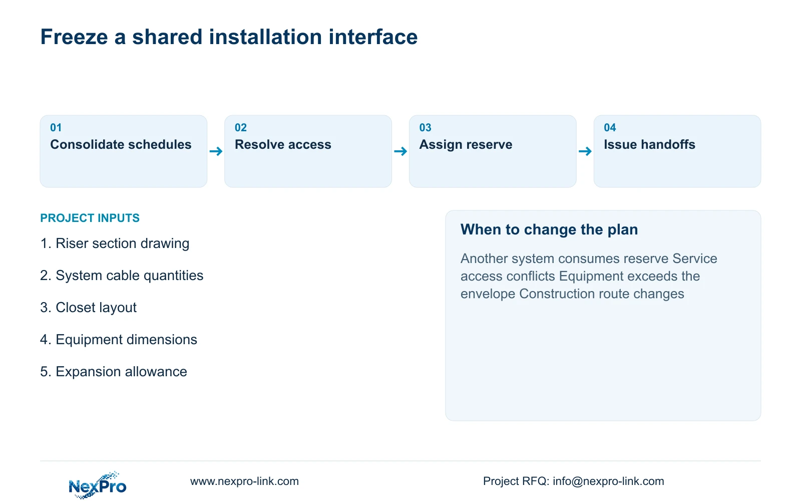
Freeze the coordinated route, termination location and access arrangement together. Confirm actual equipment dimensions and weights before committing the cabinet layout. Relevant local professionals should resolve structural support, electrical arrangements and room conditions. An equipment schedule cannot substitute for those construction decisions.
Recommend shared allocation where every participating system has a documented space assignment, usable access and an agreed handoff. Change to a dedicated arrangement, or revise the shared design, when a new system consumes the reserve, maintenance access conflicts or actual equipment exceeds the planned envelope. Keep the accepted recording and other operating tasks visible during that revision.
Send the riser section drawing, participating-system cable schedule, closet layout and intended expansion allowance to info@nexpro-link.com. NexPro-Link can discuss equipment matching, BOQ support and coordinated supply while distinguishing its CCTV manufacturing core from supporting categories. Ask the proposal to identify its supply boundaries and the installation interfaces that remain with the hotel’s project team.
Section 07
Buyer questions
Who should control unused space in a shared riser? The project should name the coordination role that maintains the consolidated allocation. Each system contributes its requirements, and any use of reserve should be recorded. Shared availability should not be assumed from an empty-looking pathway.
Does the 14U example size the riser or cable tray? No. It describes an illustrative equipment cabinet height allocation. Riser and pathway capacity require their own cable and construction inputs, while cabinet depth, load and airflow remain separate checks.
Can one equipment supplier accept all installation responsibilities? Only where those responsibilities are explicitly included and agreed. Coordinated supply or BOQ support does not automatically include pathway construction, local electrical work, termination or site testing.
Engineering references
These sources support the general planning principles. Always use the selected product's current datasheet and applicable project standards for final design.