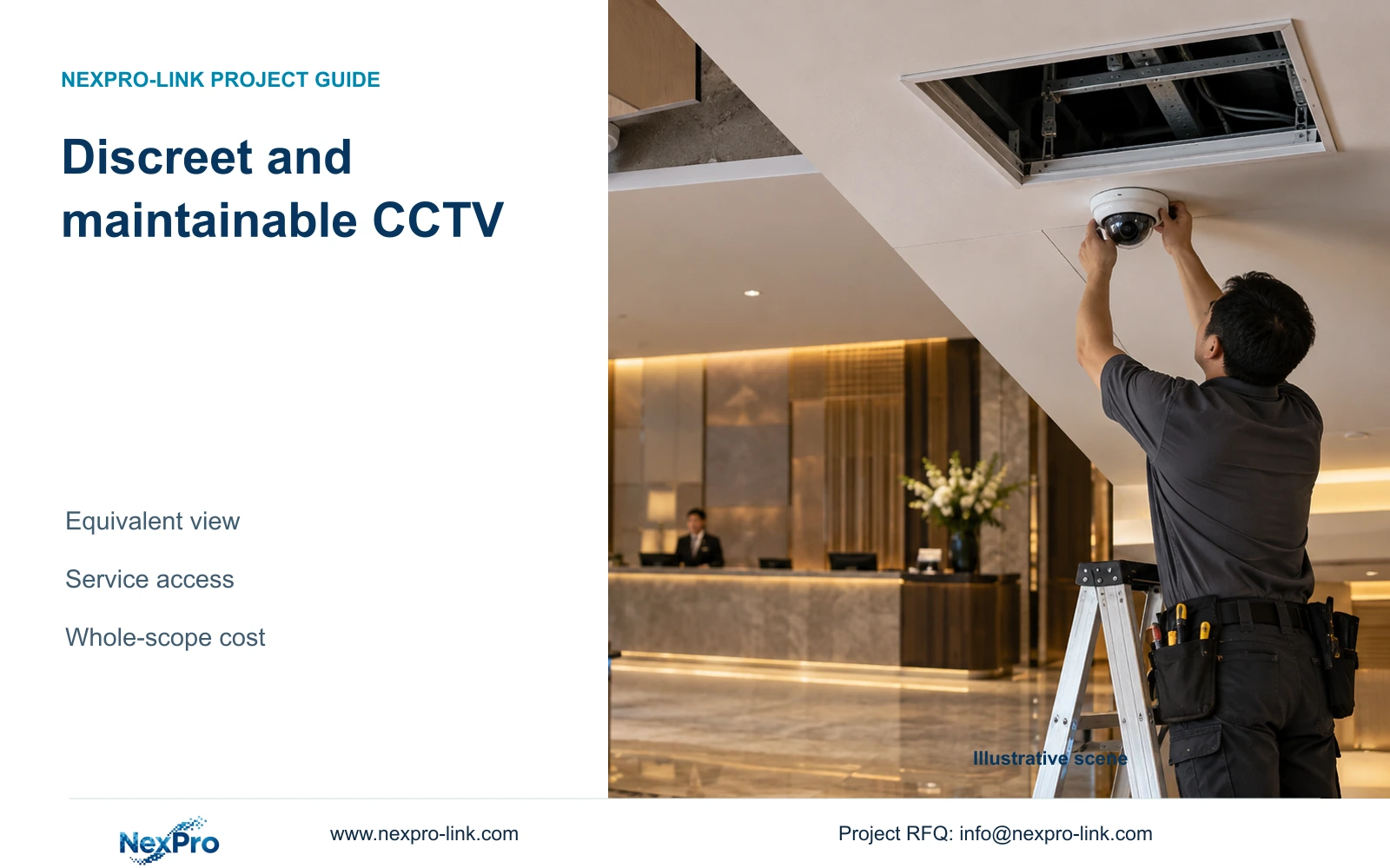
Before hotel ceilings close, connect every camera location to its mounting, cable outlet, service access and test record. Device delivery follows a separate programme.
Section 01
Fix the camera outlet and mounting interface
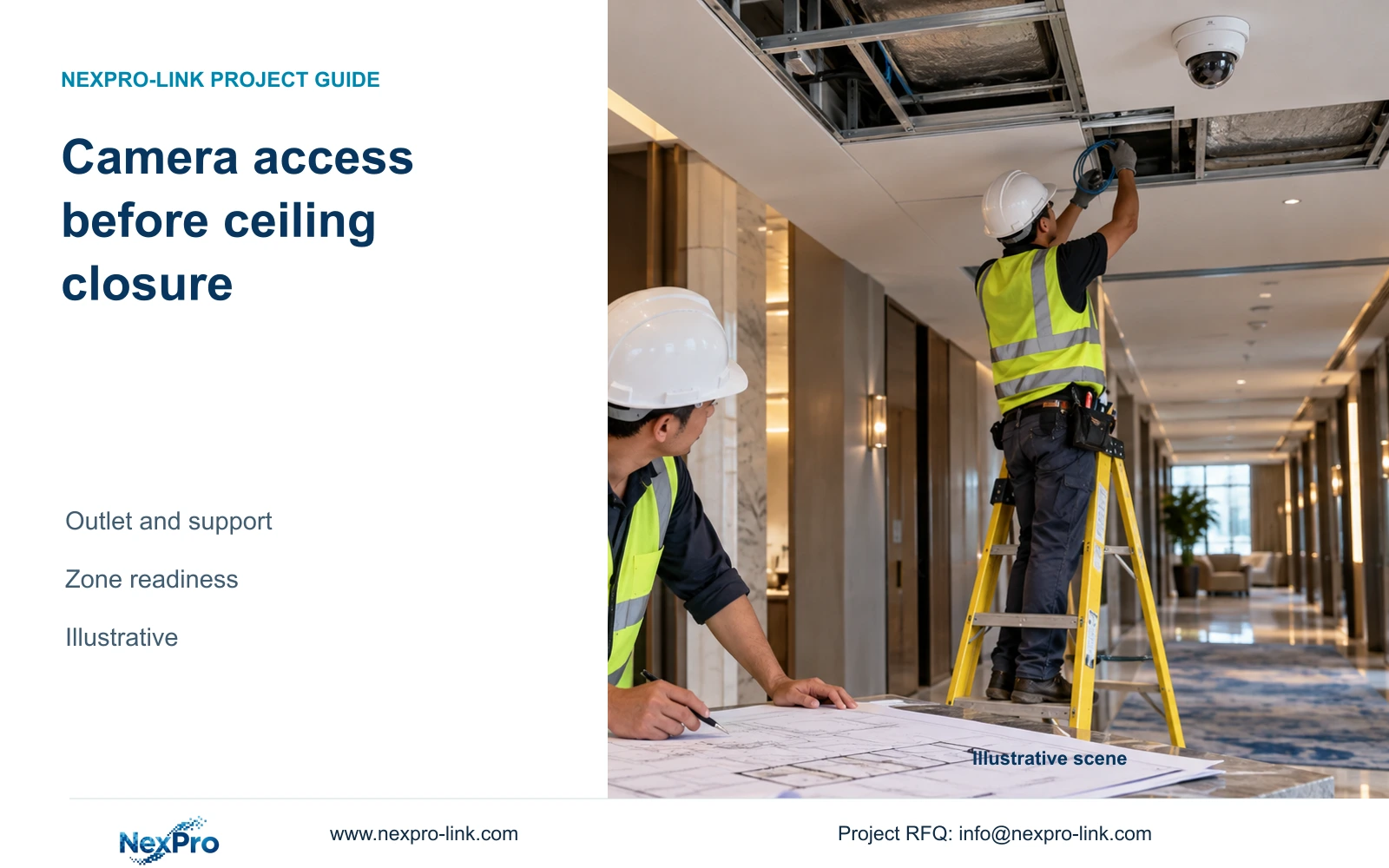
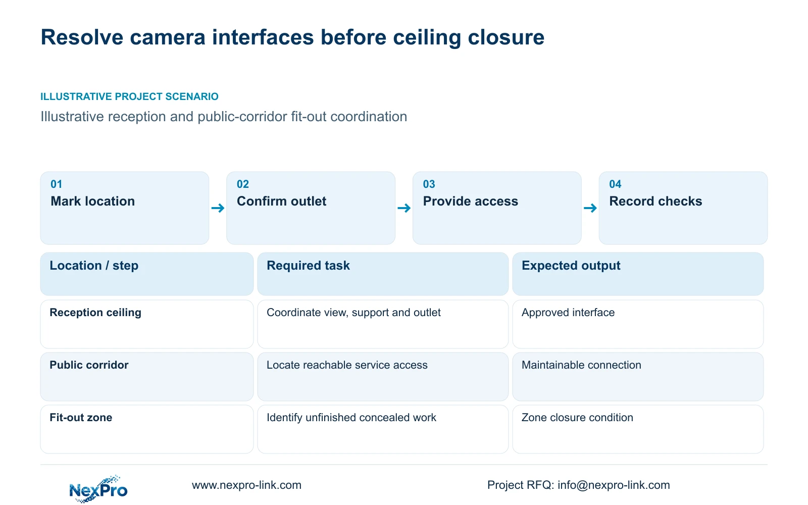
Close a hotel ceiling zone only after its camera positions, mounting interfaces, cable outlets and maintenance access are defined, with the required concealed-work checks recorded. Keep the camera schedule and reflected ceiling drawing on the same revision. If a location or support remains unresolved, hold that affected interface or use an explicitly agreed accessible arrangement.
A camera symbol does not define the installation. Mark the permitted position, mounting arrangement and connection location so the installer and fit-out team work from the same interface. For a reception view, coordinate the required observation direction with the finished ceiling layout. For a public corridor, retain the agreed view while resolving the outlet and access position.
Separate product approval from location approval. A suitable camera can still arrive with no usable support or cable outlet at its intended position. Work backward from the functions required at opening, identifying when the interface information must be available. Shipment, site arrival and an installed recording system are different milestones and should have separate owners.
| Task | Available information | Decision still needed |
|---|---|---|
| Reception camera installation | Approved observation task | Mount, outlet and service access |
| Public corridor cable connection | Camera schedule position | Route and ceiling access detail |
Section 02
Identify service access and the actual cable route
Check how the connection and mounting arrangement can be reached after finishes are complete. Place any required access opening where the relevant service task can be carried out. A nearby panel is useful only when the concealed connection is reachable through it; its presence alone does not establish a maintainable installation.
Trace cable along the available pathway, including risers, drops and termination allowances. Keep fixed lengths and patch cords separate. The supplied Fluke Networks guidance describes typical 90 m permanent-link and 100 m channel bases, with the actual category and test arrangement selected for the project. Extra concealed cable must remain visible in the route schedule.
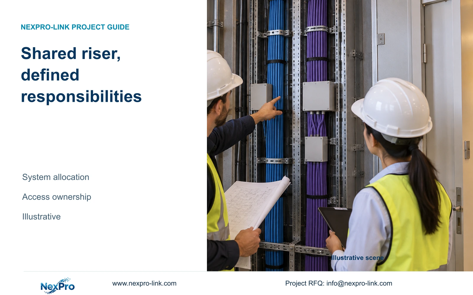
If a route requires an active node above or near the ceiling, identify its access and power source separately. Fiber carries data without automatically supplying the remote equipment. Consider an accessible closet location when servicing a concealed node would otherwise disturb finishes. The fit-out drawing should show the physical access arrangement, while the network drawing shows its operating dependency.
Section 03
Sequence cable work and tests around closure
Set the concealed-work sequence from the approved route and interface. Pull cable while the pathway is available, identify endpoints and complete the checks that require access before closure. Record incomplete termination or testing tasks with their planned accessible location and responsible party. A planned test is not a completed pass.
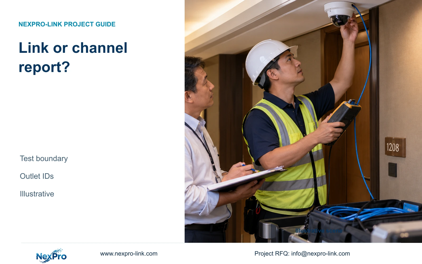
Use the actual link identity in the test record. SP5648 and DT968MX are documented Cat6 patch-panel and module candidates, respectively; neither establishes the result of an installed link. The cable, cords and connection arrangement must match the specified test basis. Record observations from the installed work instead of treating the product category as acceptance evidence.
Separate factory-reproducible checks from hotel site checks. A factory device check cannot confirm the concealed route, finished mounting position or local lighting conditions. Site acceptance should eventually confirm the actual recorded task and operating path. If a fault requires access to concealed work, correct it while the agreed access remains available and retest the affected scope under the same relevant conditions.
Section 04
Compare correction timing using real dependencies
An early outlet or route correction can be coordinated before finishes close. A late correction may require renewed access and changes to completed work. The source package supplies no measured rework price or delay, so evaluate the actual affected zone and contractor scope without assigning a universal saving.
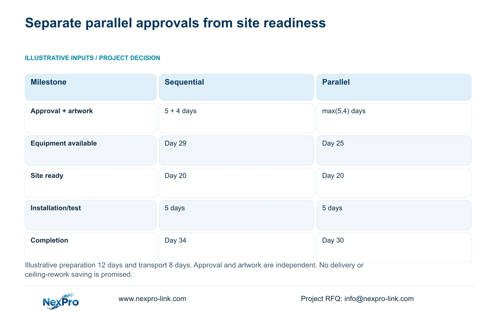
The illustrative programme assumes technical approval takes 5 days and artwork 4 days, with those branches independent. Preparation then takes 12 days and transport 8 days. Site readiness is day 20 from day zero, followed by 5 days for installation and testing. Ready-to-install day equals the later of equipment availability and site readiness.
Sequential treatment gives equipment availability at day 29 and completion at day 34. Using the stated parallel branches gives max(5,4) + 12 + 8 = day 25, then completion at day 30. This four-day difference comes from dependency treatment, not proven avoidance of ceiling rework. Use parallel scheduling only when the inputs are genuinely independent; if artwork depends on technical approval, revise the sequence.
For ceiling coordination, track concealed-work readiness separately from final equipment readiness. The supplied day-20 milestone does not prove that a zone is safe to close. A late optional display should not automatically hold a completed camera cable interface, while an unresolved essential connection can still prevent the required recording function.
| Metric / condition | All branches sequential | Actual parallel branches |
|---|---|---|
| Approval + artwork treatment | 5 + 4 | max(5,4) |
| Equipment available day | 29 | 25 |
| Site ready day | 20 | 20 |
| Illustrative completion day | 34 | 30 |
| Actual commitment | Depends on real sequence and agreed dates | Requires actual project inputs |
Section 05
Record zone-specific ceiling-close conditions
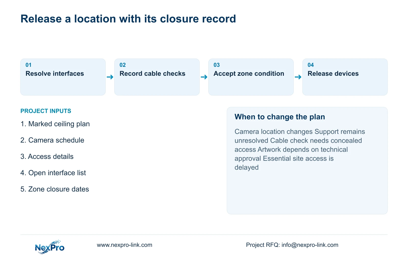
Create a closure record for the affected zone that identifies the current camera positions, support and outlet details, cable identities and relevant completed checks. Record the planned maintenance access. Any open item should state whether it affects concealed work, later device installation or final functional testing.
Name the project role that accepts the concealed-work condition and the contractor that executes closure. Equipment procurement forecasts are not an instruction to close a ceiling or place an order. The record should distinguish an approved physical interface from a supplier’s estimated delivery milestone.
Use a conditional release when part of a floor is ready and another interface remains unresolved, provided the project’s responsible team accepts that division. Hold the specific unfinished scope. Reopen the affected record when a camera position, bracket, route or access panel changes, and update the equipment schedule with the fit-out drawing.
Section 06
Release equipment against approved locations
Release devices by the accepted location schedule so the supplied camera, mount and accessories reach the correct zone. Keep technical model identity separate from floor or installation labels. Where project packing is requested, freeze the authorized artwork and variable location fields without losing equipment traceability.
Recommend phased location release when the interfaces are approved and the released package can support its intended task. Change to a later release when essential technical approval, access or site readiness remains unresolved. NexPro-Link can discuss model matching, technical documents and coordinated supply; its CCTV manufacturing core and supporting supply categories should be identified separately from local installation work.
Send the marked ceiling plan, camera schedule, unresolved interface list and zone closure dates to info@nexpro-link.com, together with the destination and required equipment-arrival milestone. The hotel project and BOQ support scopes can use those inputs for a focused proposal. Keep guest imagery and access credentials out of the inquiry.
Section 07
Buyer questions
Must every camera arrive before its ceiling zone can close? That depends on whether the approved concealed interface can be completed and checked without the device. The project team must confirm the support, outlet and later access arrangement. Device delivery alone neither authorizes nor prevents closure.
Does a factory test replace the ceiling cable test? No. Factory checks address reproducible equipment conditions. Installed cable identity, route and channel performance require their own site checks, and the completed camera task requires functional site acceptance.
Should a delayed optional display hold the camera release? Only if it is an actual dependency of the approved release. Separate optional display work from required capture, network and recording tasks, then assess whether the first package can operate as intended.
Engineering references
These sources support the general planning principles. Always use the selected product's current datasheet and applicable project standards for final design.