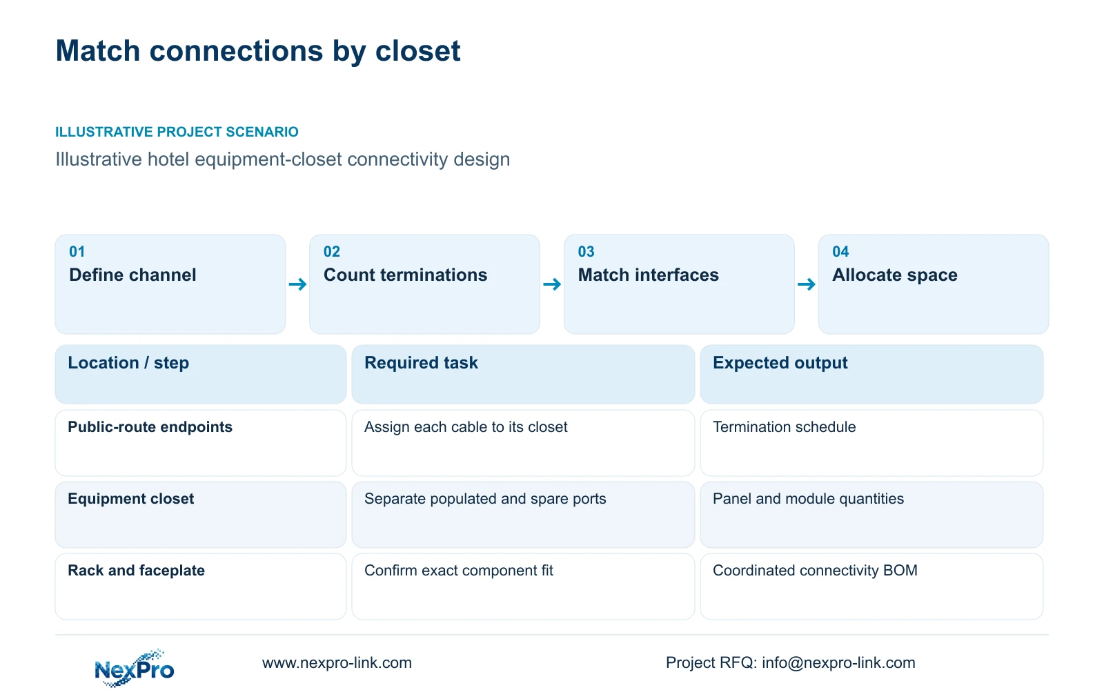
A Cat6 cable label does not qualify arbitrary modules or patch panels. Match the complete channel and allocate terminations, physical interfaces and service space by closet.
Section 01
Define the complete channel performance requirement
Select hotel CAT6 cable, modules and patch panels as a coordinated installed channel. Use SP5648 and DT968MX as references for their listed Cat6 component categories, then confirm the intended interfaces and installation arrangement. Change the proposed combination when the required category, shielding, environment or physical fit cannot be established for the whole link.
Define what each channel connects and the service it must support. Record the endpoint, closet and installed-route basis before choosing panel quantities. The supplied Fluke Networks record distinguishes the typical 90 m permanent link from the 100 m channel including patch cords. The project still needs its own connection arrangement and acceptance configuration.
A cable, panel and module sharing the Cat6 label provide component information, not proof that the installed channel has passed its specified tests. Include the cable and cords, connection identities and workmanship in the acceptance scope. For an existing installation, preserve the relevant records before proposing replacements so the buyer can distinguish a deficient component from an incomplete installation.
| Required task | Given information | Decision still needed |
|---|---|---|
| Connect camera to assigned closet | Endpoint and route schedule | Complete channel and test basis |
| Maintain equipment access | Proposed rack location | Physical interfaces and service space |
Section 02
Count active, spare and future terminations separately
Count the cable endpoints assigned to each actual closet. Separate active terminations from installed spare links and unpopulated future panel positions. These quantities have different material requirements. An empty panel position does not provide a cable route, module, patch cord or switch port unless those items are included separately.
For four illustrative closets with eight active camera links each, assign eight cabinet-side terminations to each closet, not one 32-link total at the central room. Request the panel's supplied population separately: does its price include the required connectors, or only capacity? Count the camera-end connection and patch cords by their actual arrangement. Do not assume every connection uses DT968MX or that it fits SP5648.
SP5648 has 48 ports in its listed Cat6 patch-panel description. That count is a component property, not an instruction to concentrate every hotel endpoint in one cabinet. The complete hotel reference distributes its camera connections among four access nodes; its topology illustrates why quantities must follow the actual closet assignments.
Avoid applying one spare percentage to every resource. Additional panel capacity, spare modules, unused switch ports and reserved rack space address different changes. Describe the intended expansion event and identify what would be purchased now. If no future route is defined, keep that allowance distinct from active installed links so the owner can see what the initial order delivers.
Section 03
Match category, construction and component interfaces
The source lists SP5648 as a Cat6 48-port data patch panel and DT968MX as a Cat6 tool-free module. Neither is a bulk-cable SKU. Use those identities accurately in the bill of materials and specify the cable by the required conductor, category, jacket conditions and supplied length.
Request the exact mating and construction information for the selected arrangement. A module's category does not establish that it fits every panel or faceplate. Likewise, the listed component descriptions do not establish an entire shielded channel. Where shielding or outdoor conditions are required, coordinate the corresponding connections and installation design instead of extrapolating missing properties.
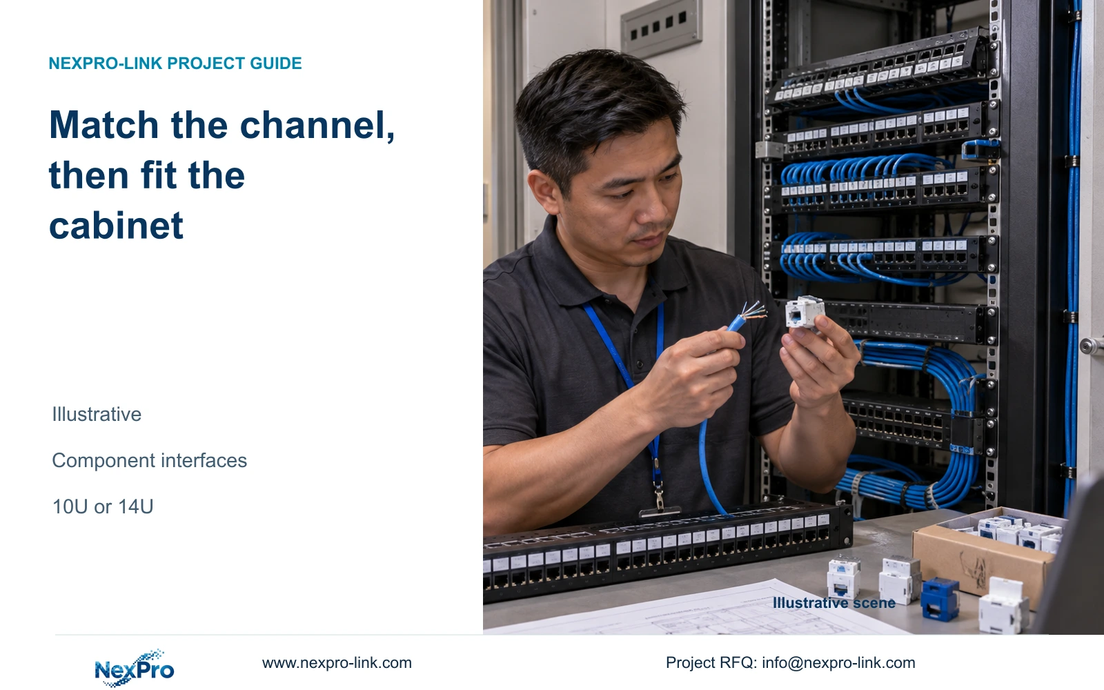
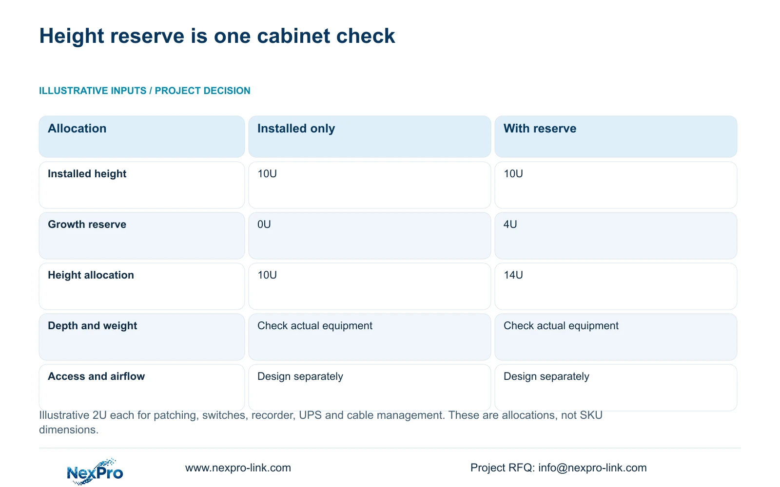
Reserve the supporting resources alongside the component count. The rack example assigns 2U each to patching, switches, recorder, UPS and cable management. Those five assumed allocations total 10U, with an optional 4U growth allowance. They are planning inputs, not the published dimensions of SP5648, a recorder or any UPS model.
Section 04
Check rack, faceplate and maintenance fit
Confirm the mechanical format at both ends of the channel. At the closet, review panel mounting, cable entry and patch-cord management. At the endpoint, check the selected module and its faceplate or connection arrangement. These checks need actual component information; a photograph or category label cannot settle every mounting interface.
Calculate planned rack height as installed allocations plus explicit reserve. The example gives 10U for current equipment and 14U when the stated 4U reserve is retained. That result sets a height allocation only. Actual depth, equipment weight, cable bends and service access can require a different cabinet even when the nominal U-space appears sufficient.
UPS and battery support must follow the selected equipment's installation requirements and cabinet loading arrangement. Review front and rear access before fit-out restricts the room. Local structural, electrical and cooling professionals address their respective interfaces. An unused rack position is not evidence that heavy equipment can be supported or that the cabinet's airflow is adequate.
| Metric / condition | Installed equipment only | Installed plus planned reserve |
|---|---|---|
| Allocated installed height | 10U | 10U |
| Reserved growth space | 0U | 4U |
| Minimum height allocation | 10U | 14U |
| Depth / load / airflow | Must still be designed | Must still be designed |
Section 05
Compare populated and expandable layouts
A fully populated layout can provide the defined active connections at handover, while an expandable layout reserves resources for stated later work. Compare them with the same initial operating task. Show which modules, cords and panel positions are populated now and which additional items are needed to activate future endpoints.
Retain the illustrative 4U reserve when the proposed growth and service arrangement justify it. Choose a different allowance when actual equipment dimensions or expansion requirements change. The 14U result is neither a universal cabinet size nor the full rack schedule for the separate complete hotel case. Its purpose is to make space decisions visible alongside connectivity quantities.
Compare the installed scope, including cable management and access, before considering cabinet price. Wall-mounted and floor-mounted arrangements can create different support and maintenance requirements. Expansion space must remain usable after cable bundles and equipment are installed. Review cooling from the real equipment and room conditions rather than assuming additional empty U-space resolves every thermal constraint.
Section 06
Create a closet-by-closet connectivity BOM
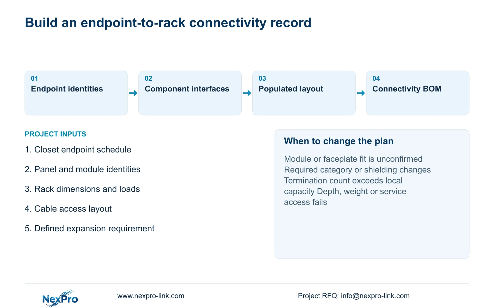
Build the connectivity bill of materials around endpoint and closet identities. List continuous cable quantities, panel capacity, populated modules, patch cords and the associated management hardware. Identify installation and testing separately, and keep electrical support and cabinet loading within their responsible professional scopes. Remove duplicate accessories already included in a supplied package before totaling quantities.
Recommend a coordinated Cat6 package when its component interfaces, installation conditions and acceptance basis meet the required service. Enlarge or redistribute the layout if the actual termination count, equipment depth or access requirements exceed the proposal. Change category or shielding only when the defined channel requirement calls for it, with the corresponding component and installation changes included.
Send the closet endpoint schedule, proposed component identities, rack dimensions and expansion requirement to info@nexpro-link.com, with the delivery destination. NexPro-Link can discuss model matching and coordinated BOQ support around its CCTV manufacturing core and supporting supply scope. The supplied policy gives applicable main equipment a 24-month limited hardware baseline from receipt; cable and other accessory terms follow their scope and written order, so do not extend that baseline automatically to every connectivity item.
Section 07
Buyer questions
Does one 48-port panel cover a 32-camera hotel? Its port count alone cannot settle the layout. Allocate terminations by actual closet and route. A distributed design may need panel capacity at several locations, with modules, cords and switch ports counted independently.
Can DT968MX be specified for any Cat6 faceplate? Its listed category and tool-free description do not establish every mechanical fit. Confirm the selected faceplate or panel interface from the exact component information before approving the combination.
Is a 14U cabinet the finished recommendation? No. Fourteen U is the example's height allocation after adding 4U reserve to 10U of assumed equipment space. Actual dimensions, load support, airflow and service access can dictate another cabinet.
Engineering references
These sources support the general planning principles. Always use the selected product's current datasheet and applicable project standards for final design.