Select shielded hotel CAT6 only as a coordinated channel. Compare the actual interference concern, component interfaces and electrical responsibilities before paying for cable alone.
Section 01
Identify the interference concern before choosing shielding
Choose shielded CAT6 when the project identifies a reason for it and can provide a coordinated channel, including matching connections and the required electrical design. Retain an appropriately specified unshielded channel where it meets the route and operating requirements. Buying shielded cable alone leaves the proposed shielding arrangement incomplete and does not establish that the hotel has solved an interference problem.
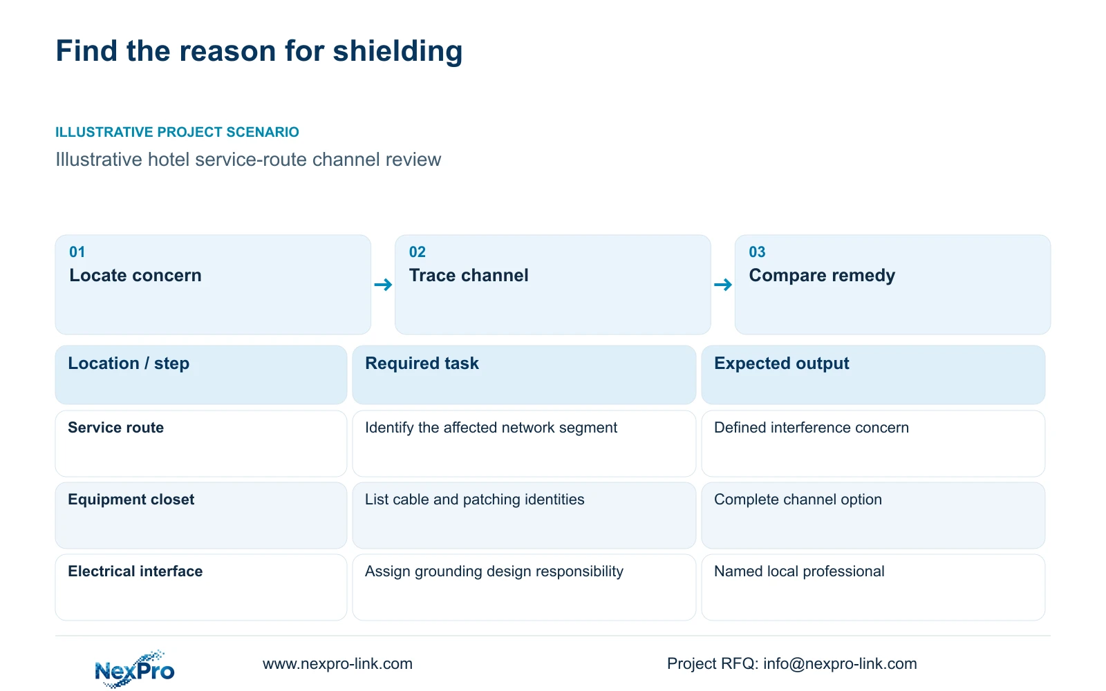
Locate the concern on a drawing. Record the affected network endpoint, the nearby installation condition and the service that must remain available. Distinguish a proposed precaution from an observed operating symptom. For an existing installation, preserve relevant fault records so the team does not assume every interrupted camera view originates in the cable.
Trace data and power separately. A camera can lose service because an intermediate node is unprotected during an outage, even when the transmission path is otherwise suitable. Include installed length and connection identity in the initial review. These inputs help the designer decide whether shielding, a changed route or a different backbone is the appropriate response.
| Required task | Given information | Decision still needed |
|---|---|---|
| Maintain service-route recording | Interference concern identified on route | Complete channel or route change |
| Maintain outage recording | Intermediate network node present | Protection of that node's power |
Section 02
Compare complete channels and alternative routes
Evaluate an unshielded channel and a shielded channel using the same endpoints, network service and installation scope. Include cable, modules, panel connections and patch cords. A cable-only comparison omits the parts and work needed to deliver the selected arrangement, so its apparent price difference cannot support the final procurement decision.
A route change deserves a separate option. Moving a closet or using a fiber backbone can alter the length and building interfaces, but may introduce active equipment and local power. Retain the required recording and outage behavior in every alternative. Otherwise, the buyer would be comparing different services under similar cabling descriptions.
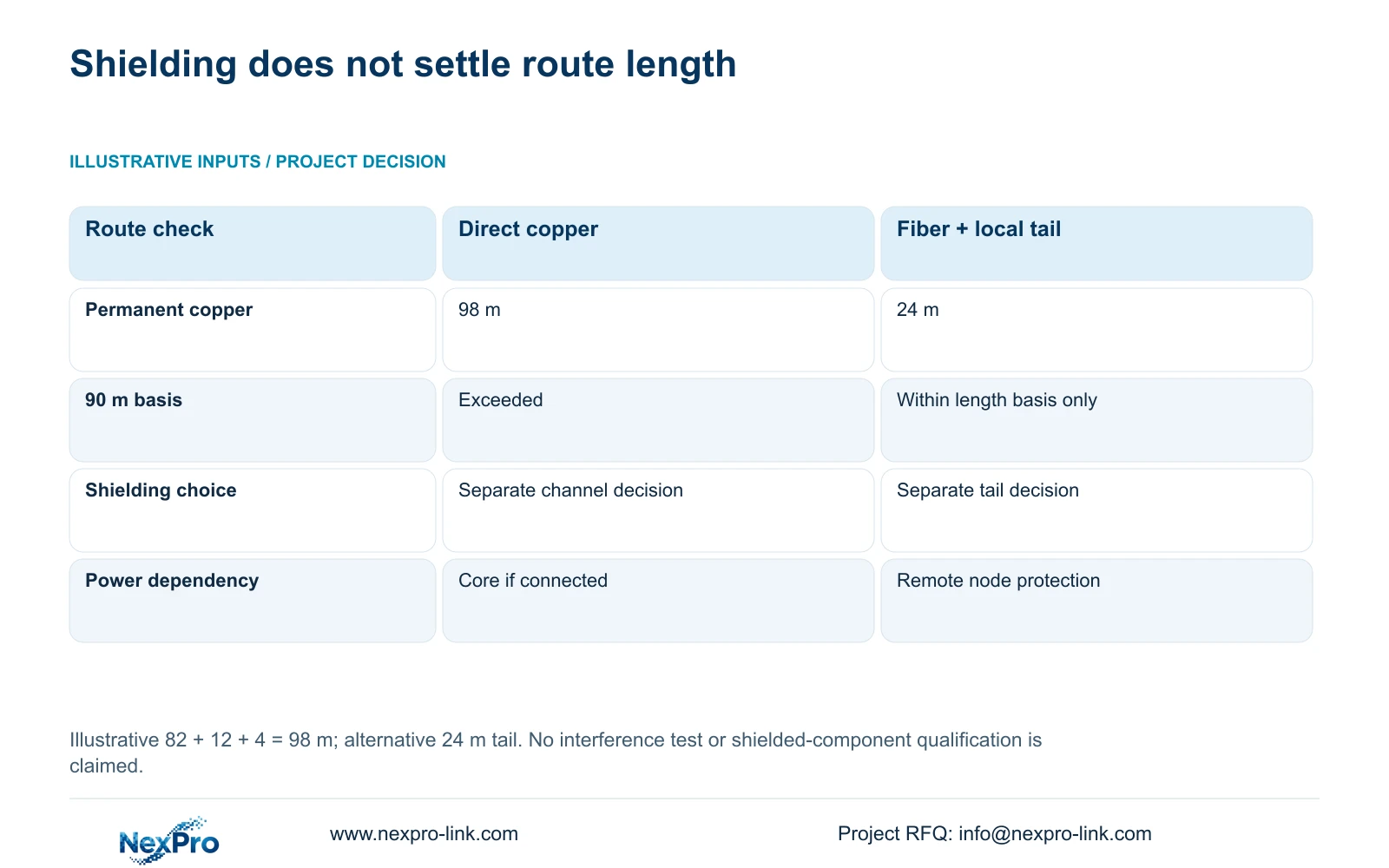
The illustrative route consists of 82 m horizontally, 12 m vertically and 4 m of termination allowance. Permanent length equals the sum of those parts, giving 98 m. The qualified fiber-node alternative uses a 24 m local copper tail. Shielding does not remove the original length issue, so this scenario requires a route decision before a shielding choice can qualify the copper portion.
| Metric / condition | Direct copper route | Qualified fiber node + local copper |
|---|---|---|
| Planned copper permanent route | 98 m | 24 m |
| Typical 90 m permanent-link basis | Exceeds this basis | Within length basis only |
| Extra active dependency | None assumed | Remote switch and local power |
| Backup boundary | Core supply if fully connected | Remote node must also be protected |
Section 03
Match modules, panels and patch cords
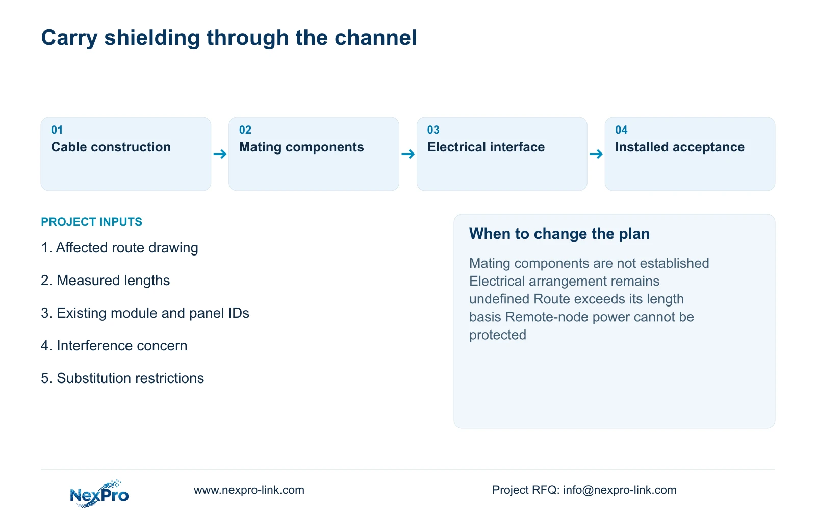
Create a component schedule for each proposed channel. Name the cable construction and its intended module, panel and patch-cord arrangement. Request the relevant interface information before accepting substitutions. The presence of Cat6 in several descriptions does not establish that every mechanical interface or shielding detail has been coordinated.
SP5648 is listed as a Cat6 48-port patch panel, and DT968MX as a Cat6 tool-free module. These are useful category references. The supplied records do not establish the shielding construction or every mating interface needed for this proposal, so neither should be declared a qualified shielded component from its name alone. SP5648 is also not a bulk-cable model.
Keep the route-length calculation separate from the component evidence. The 98 m and 24 m values are assumed installation distances, not dimensions or performance results for either SKU. A revised bill of materials should identify which connections change when shielding is selected and which existing items can remain after their compatibility has been checked.
Section 04
Coordinate shielding continuity through every connection
Represent the intended shield path across the cable and its connections, including patching interfaces. Each component must have a defined role in the selected channel design. An unspecified connection leaves a gap in the design evidence, even if the bulk cable itself has the requested shielding construction.
Fluke Networks describes a specific false-confidence risk: with grounded panels at both ends, a basic continuity test may follow the common building ground and report a connection despite an open cable shield. Ask how the proposed test distinguishes the cable's shield path from that parallel path. This testing principle does not prescribe the hotel's bonding design or certify its components.
The installation method and acceptance scope should describe how the completed arrangement will be checked. Keep transmission testing and the electrical design responsibilities visible; one does not substitute for the other. Avoid prescribing a universal grounding arrangement from a purchasing article. The correct details belong to the selected system and the responsible local professionals.
In the illustrative route comparison, 24 m removes the stated copper-length problem, while 98 m exceeds the typical 90 m permanent-link basis described in the supplied Fluke Networks record. The shorter tail still needs a qualified channel. The table offers no evidence that either shielded or unshielded cable has passed an interference test, and its values are independent of the complete hotel reference case.
Section 05
Separate electrical design from network component supply
Assign the network designer responsibility for the communication path and component schedule. Identify the local professional responsible for grounding, bonding and electrical protection where these affect the installation. The supplier can provide equipment information and clarify supply boundaries, but a combined equipment order does not establish the site's electrical design.
Fiber introduces a distinct power boundary. Its remote active node needs an appropriate source, and that source must be protected if the agreed camera service must continue during an outage. Explain who installs, powers and services the node. Include its enclosure and access provisions in the alternative's cost and maintenance scope.
If NexPro SW-POE1618G is proposed, treat it as an inquiry candidate. The source describes 16 PoE ports, two uplinks and af/at support, but conflicts between title and detailed access-port speed fields remain, and total PoE wattage is missing. The project must obtain an explicit response to required speed and power before assigning that candidate a qualified role.
Section 06
Price the qualified installed system
Compare evaluated scope totals after adding the matching connections, installation work, required testing and electrical interfaces. Show a fiber-node option separately with its active devices and protected local power. No actual quotation or measured performance advantage is established by this example; the buyer needs scope-matched supplier and installation responses.
Select a complete shielded channel when the identified concern and project requirements justify it and the component and electrical arrangements are defined. Retain the qualified unshielded option when it satisfies those requirements. Change the topology when installed length or building interfaces invalidate direct copper, and reconsider a remote-node option if local power or maintenance access is unavailable.
Send the affected route drawing, measured lengths, interference concern and existing component schedule to info@nexpro-link.com, with any substitution restrictions. NexPro-Link can discuss model matching and coordinated BOQ support around its CCTV manufacturing core and supporting supply scope. Local installation and electrical responsibilities should remain named in the proposal, so the selected cable construction can be carried into an executable channel design.
Section 07
Buyer questions
Can we keep existing modules after buying shielded cable? Only after their role in the selected channel is confirmed. Ask for the exact module and panel identities, shielding details and mating interfaces. A matching category label alone is insufficient evidence for that substitution.
Does shielded CAT6 extend the normal permanent-link length? The supplied comparison provides no such allowance. Its 98 m permanent route exceeds the stated typical 90 m basis regardless of the shielding purchase, so revise the route or evaluate a qualified backbone alternative.
Who should define the grounding arrangement? The responsible local electrical professional should coordinate it with the chosen channel and installation requirements. Request that responsibility explicitly in the proposal instead of assuming it is included in a cable supply order.
Engineering references
These sources support the general planning principles. Always use the selected product's current datasheet and applicable project standards for final design.