Hotel camera positions become a reliable cable order only after actual pathways, vertical sections and termination allowances are measured and assigned to continuous reel cuts.
Section 01
Choose the installable horizontal route
Order hotel CCTV cable from individual installed routes and a feasible continuous-cut plan. Use a total-meter estimate for preliminary budgeting only until the ceiling pathways, risers and termination allowances are known. A straight line between a camera symbol and a cabinet leaves out the route the installer can actually use, so it can understate both purchasing quantities and link length.
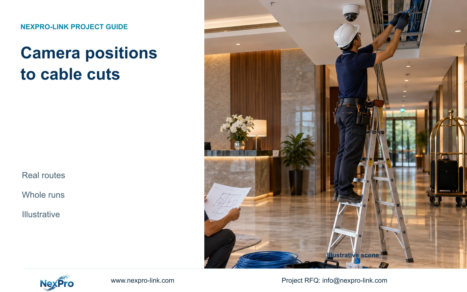
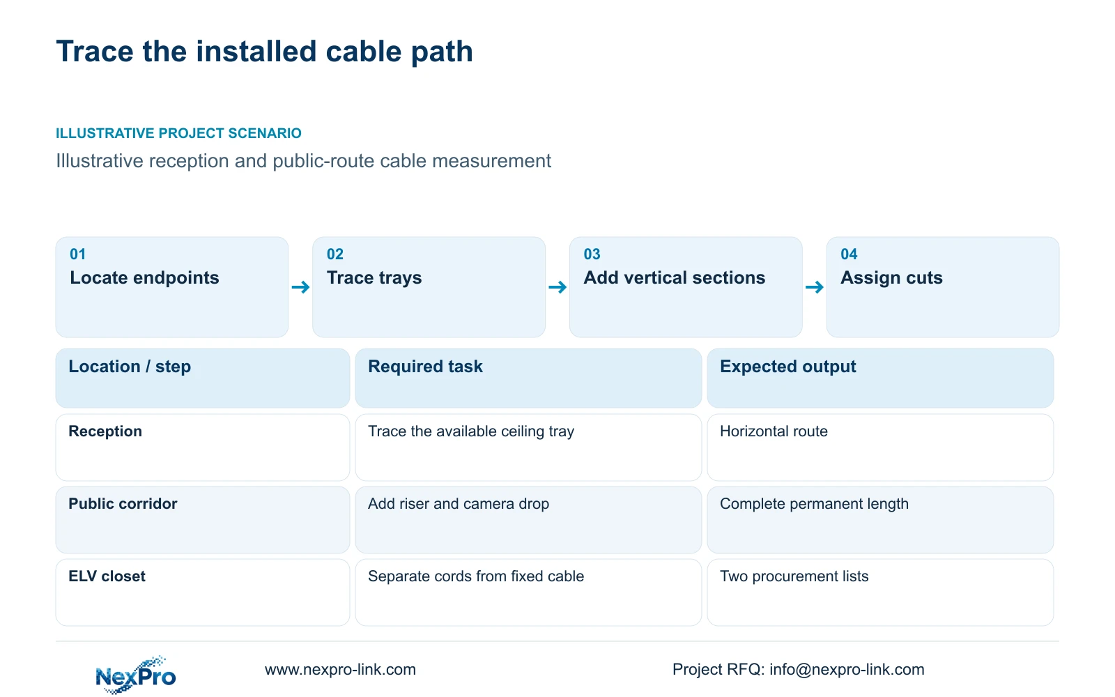
Trace each public-area camera along the proposed tray or conduit to its assigned closet. Reception views may share a ceiling pathway before separating toward individual mounting positions. A parking camera may require a different route through an exterior service area. Record those branches explicitly, including any detour around inaccessible finishes or a building boundary.
Assign the route to a drawing revision and identify who can confirm its availability. A pathway shown on an early plan may conflict with later services or access restrictions. Where the route remains provisional, carry that uncertainty against the affected camera ID. This lets the buyer distinguish a measured quantity from an allowance without applying an unexplained percentage to the whole hotel.
| Required task | Given information | Decision still needed |
|---|---|---|
| Reception camera connection | Camera and closet positions | Available ceiling tray route |
| Parking camera connection | Exterior endpoint | Building crossing and power boundary |
Section 02
Add vertical sections and stated termination allowances
After selecting the horizontal pathway, measure the vertical portions separately. Include the rise into a shaft, the floor-to-floor route and the drop from the ceiling pathway to the camera connection. These sections can be absent from a plan-view measurement even when the camera and cabinet appear close together.
Use identifiable fields for horizontal length, vertical length and termination allowance. The allowance should describe the intended connection or service arrangement. If the scheduled permanent route already includes that allowance, the purchasing calculation must use the same complete length. Adding an unrecorded service loop later changes the installed link and can invalidate an earlier length decision.
Compare an accessible termination position with a concealed connection that requires a longer approach. The accessible position may reduce future disturbance to finishes, while a different cabinet entry can change the cable drop and bend space. Decide these interfaces before cutting cable. A longer scheduled route can be acceptable when it remains within the chosen design basis and provides the required access.
Section 03
Keep permanent cable and patch cords in separate totals
The permanent link and the complete channel have different measurement boundaries. Fluke Networks guidance describes the typical 90 m permanent-link basis and the 100 m channel basis that includes patch cords. Apply the project’s actual category, connection arrangement and test configuration when assessing a route. These figures do not certify a cable installation by length alone.
List cabinet patch cords and equipment cords separately from the continuous fixed cable. That separation supports both procurement and testing: reel quantities relate to fixed runs, while cord quantities relate to the selected port arrangement. It also prevents a scheduled 90 m permanent run from silently acquiring additional fixed cable under a patch-cord allowance.
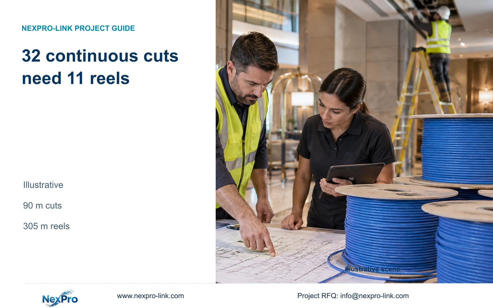
For the illustrative calculation below, every one of the 32 runs is a complete 90 m permanent route. Each already contains its planned installation allowances. The procurement lower bound is the total cut length divided by the 305 m reel length, rounded upward. Feasibility then requires allocating whole runs to individual reels. These are teaching inputs, independent of the linked complete hotel reference.
Section 04
Calculate whole cuts before choosing the reel quantity
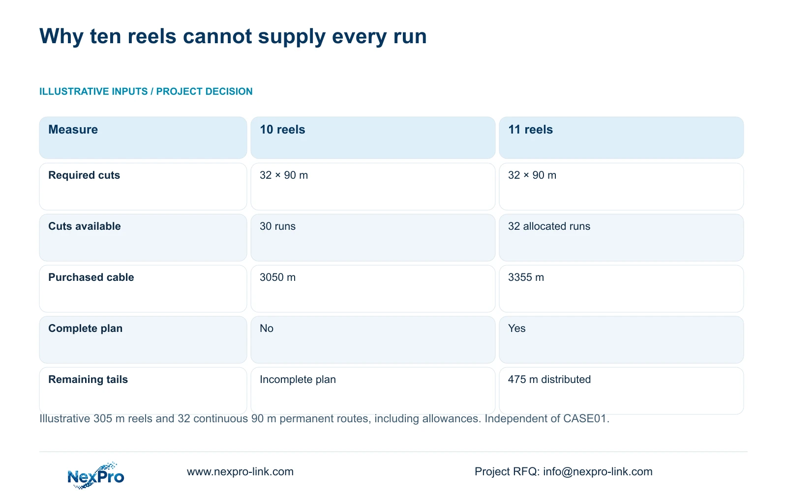
The illustrative total is 32 × 90 m = 2,880 m. Dividing by 305 m and rounding upward gives 10 reels. However, each reel can provide only three complete 90 m cuts: floor(305/90) = 3. Ten reels therefore supply 30 runs, leaving two camera connections without continuous cable.
Eleven reels provide a feasible plan. Cut three runs from each of the first ten reels and two from the final reel. Purchased length becomes 11 × 305 m = 3,355 m. Subtracting the 2,880 m installed cut requirement leaves 475 m distributed across the reels. Those pieces cannot be treated as a single spare cable or joined arbitrarily to complete a standard run.
Select 11 reels for these exact assumptions. Recalculate when the actual run list or purchased reel length changes. A mixed schedule may use tails more effectively than this equal-length example, but the allocation must demonstrate that every required continuous run fits. The complete illustrative hotel case uses different route lengths and quantities; its cable totals must remain separate.
| Metric / condition | Rounded lower bound | Feasible continuous-run plan |
|---|---|---|
| Total cut length (m) | 2880 | 2880 |
| 305 m reels | 10 | 11 |
| Can every run be cut? | No: 10 reels fit only 30 runs | Yes: 10×3 runs + 1×2 runs |
| Purchased length (m) | 3050 | 3355 |
| Total remaining tails (m) | Not a feasible complete plan | 475 |
Section 05
Compare shorter routes with their added dependencies
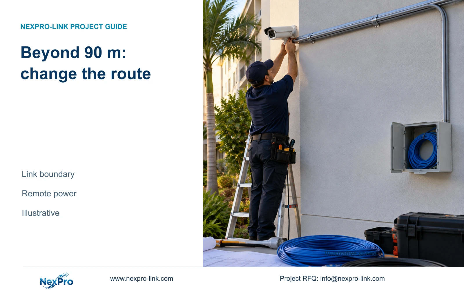
A route that exceeds the selected length basis needs a design change before cable procurement. In a separate illustrative path example, 82 m horizontal + 12 m vertical + 4 m termination allowance produces a 98 m permanent route. That exceeds the typical 90 m basis. Changing the reel order cannot resolve this link-design problem.
Compare an adjusted closet position with a suitable fiber backbone and a 24 m local copper tail. The shorter tail removes the stated copper-length issue, but the remote switch needs an appropriate power source, enclosure and maintenance access. Fiber carries data and does not automatically deliver power to the remote camera.
Retain the required recording behavior during the agreed outage when evaluating either option. If the new remote node is necessary for recording, its power protection belongs in the revised scope. Prefer a simpler compliant route when it is available. Choose the remote-node arrangement when the physical pathway cannot be shortened and the hotel can support its local power and service responsibilities.
Section 06
Issue a cable schedule that connects cuts to test records
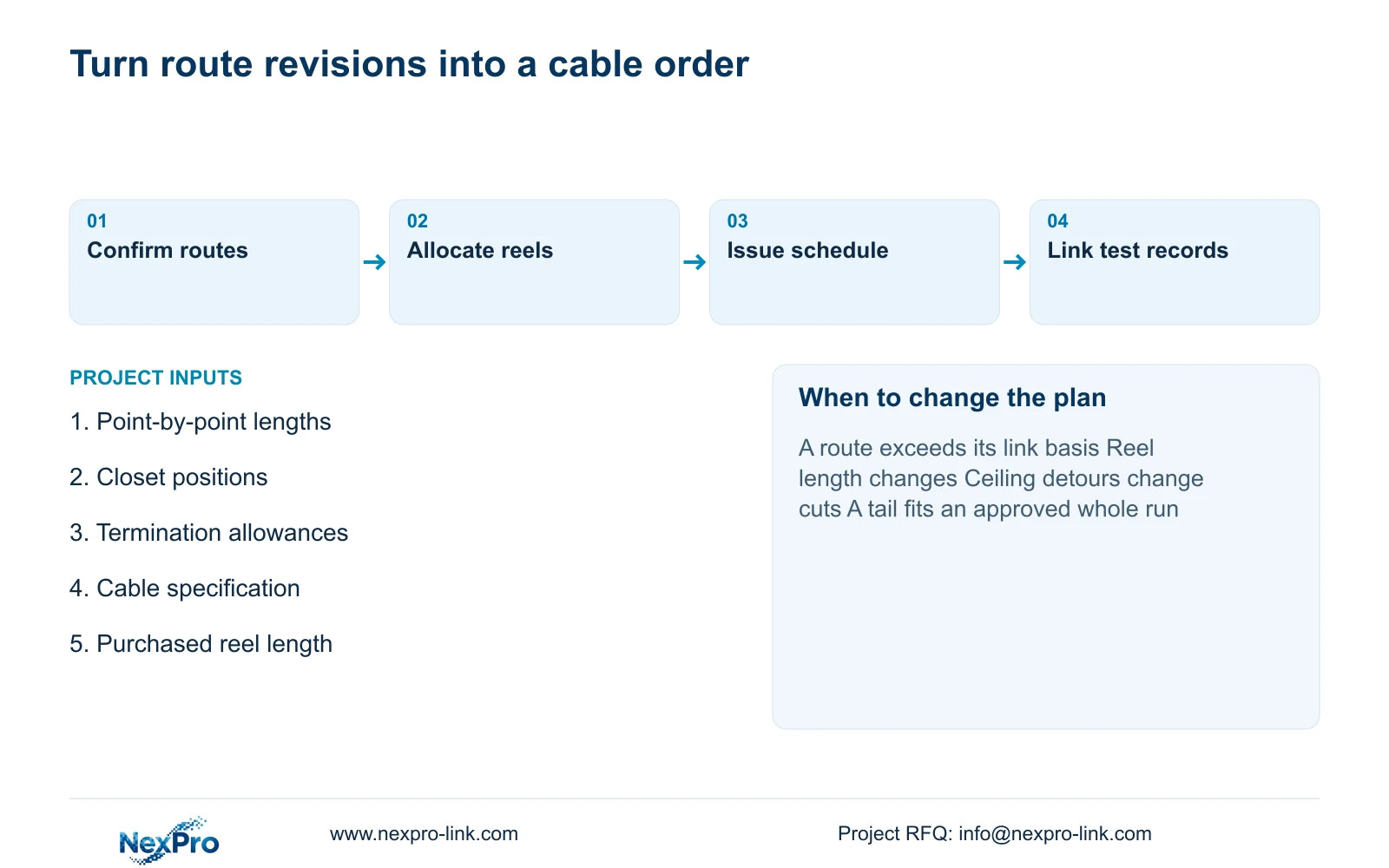
The final schedule should connect each camera ID to its origin and destination ports, complete permanent-route length and assigned reel cut. Link the installed identity to the test record so that a failed or changed connection can be located without interpreting an aggregate cable quantity. Keep the current route revision with the schedule.
Specify the bulk cable’s conductor requirements, category, jacket, reel length and destination requirements. SP5648 is a Cat6 48-port data patch panel, and DT968MX is a Cat6 tool-free module. Neither is a bulk cable SKU, and their category labels do not establish the performance of the entire installed channel.
Send the measured route list, closet positions, termination allowances and destination cable specification to info@nexpro-link.com through the hotel project or BOQ support scope. NexPro-Link can discuss component matching and coordinated supply. Local pathway installation and testing responsibilities should be stated separately. Reissue the cut plan whenever a route change alters a continuous length or crosses the approved link basis.
Section 07
Buyer questions
Can leftover reel tails reduce the next cable order? Yes, when an identified tail is long enough for a complete approved route and meets the cable specification. Record its usable length and allocate it to a specific run. Distributed tails are not an interchangeable total-meter credit.
Can an average route length support an early quotation? It can support a clearly provisional allowance. Ask the quotation to distinguish that allowance from a final cut list and identify which routes still need measurement. Confirm whole-run feasibility before ordering reels.
Does a Cat6 patch panel prove the camera link is Cat6? No. The cable, modules, cords, connection arrangement and installed-link test must support the specified channel. SP5648 describes the patch panel, not a completed installation or bulk cable.
Engineering references
These sources support the general planning principles. Always use the selected product's current datasheet and applicable project standards for final design.