Record whether the excessive length is estimated, surveyed or already installed. Give each status its next action: verify the route, revise the design or assess the installed connection under the approved test basis.
Section 01
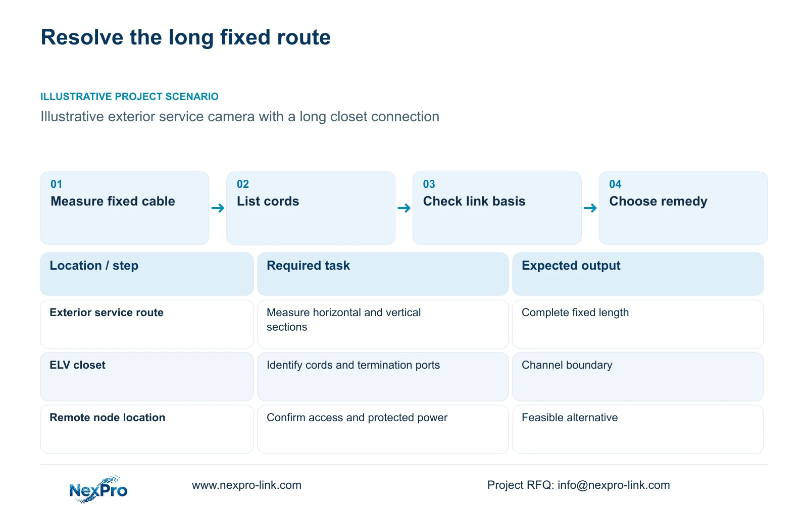
Measure the complete fixed route first
Record whether the excessive length is estimated, surveyed or already installed. Give each status its next action: verify the route, revise the design or assess the installed connection under the approved test basis. Preserve the earlier drawing and resulting BOQ change. A working camera cannot retrospectively approve an overlength design.
When a hotel camera’s permanent route exceeds the typical 90 m basis, revise the route or select an explicitly supported alternative before procurement. First separate fixed cable from equipment cords. Prefer a shorter compliant route where one is available; use a qualified remote fiber node when the pathway cannot be shortened and its local power and maintenance conditions can be met.
Measure along the installable pathway from the assigned closet to the camera connection. Include shaft travel, ceiling detours and termination allowances. A camera at an exterior service route can be close to the equipment room on a plan yet require a much longer installed path. Mark any inaccessible or unresolved section against that camera ID.
Establish the measurement status as drawn, surveyed or installed. An estimated route near its limit needs confirmation before the cut list is released. Keep the permitted observation position fixed while examining cable remedies. Moving a camera solely to shorten cable may lose the required entrance or parking view, so any position change must retain the approved task.
| Task | Available information | Decision needed |
|---|---|---|
| Exterior service view | Camera position and estimated route | Confirm full fixed length |
| Public corridor view | Required observation task | Can the closet route be shortened? |
Section 02
Add equipment cords without changing the measurement boundary
Create separate schedule fields for the permanent route and the cords that complete the channel. The supplied Fluke Networks guidance describes a typical 90 m permanent-link basis and a 100 m channel basis including patch cords. The remaining channel allowance is not permission to hide additional fixed cable inside the cord total.
Show the cabinet patch-panel connection, switch cord and camera-end connection as actually proposed. SP5648 is a Cat6 48-port patch panel, and DT968MX is a Cat6 tool-free module. Those component descriptions do not establish a passing complete channel or a supported extended-distance arrangement.
If an extra switch or extender is proposed, draw it as an active dependency with its interfaces and power source. It changes the topology and the service path. Keep each copper segment’s length explicit and identify the equipment that supports the proposed arrangement. A 305 m cable reel describes purchased stock length; it is not a camera transmission-distance specification.
Section 03
Check the route against its specified link design
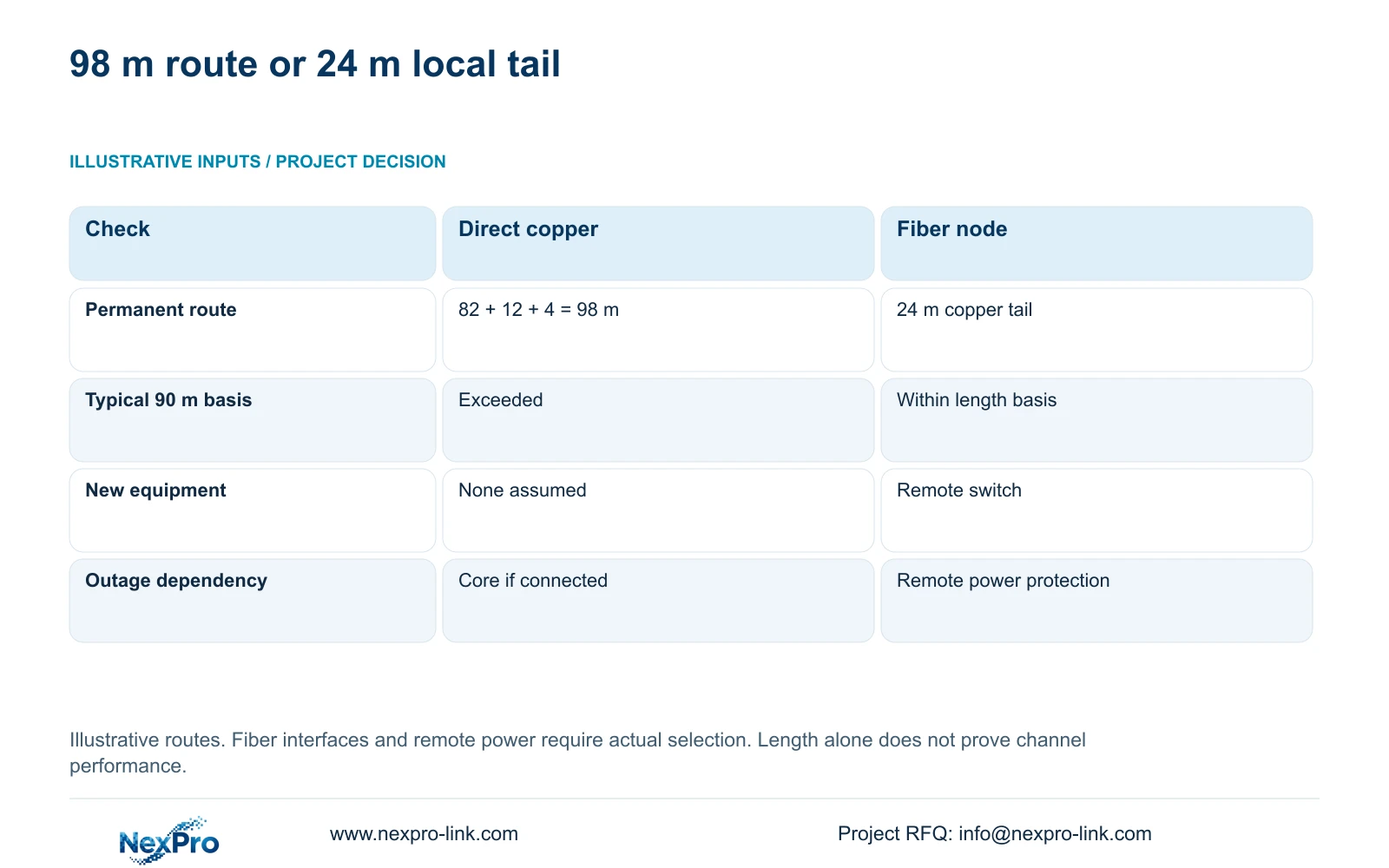
The illustrative fixed route contains 82 m horizontal, 12 m vertical and 4 m termination allowance. Permanent route length equals the sum of those sections, giving 98 m. It exceeds the stated typical 90 m basis before equipment cords are considered. The calculation identifies a design issue, without predicting exactly how an unsupported installed connection would behave.
Compare it with a qualified fiber node followed by a 24 m local copper tail. The alternative removes the stated copper-length issue, while introducing a remote switch and local power. Being within the length basis is only one condition: the cable category, environment, connection arrangement and testing must also suit the selected application.
Use these results to exclude the unchanged 98 m route from an ordinary 90 m permanent-link proposal. Do not claim an exception from a camera being online during a brief check. Any extension approach needs its own supported equipment limits and acceptance basis. These route inputs are independent of CASE01 and do not amend that reference hotel’s cable quantities.
| Metric / condition | Direct copper route | Qualified fiber node + local copper |
|---|---|---|
| Planned copper permanent route (m) | 98 | 24 |
| Typical 90 m permanent-link basis | Exceeds this basis | Within length basis only |
| Extra active dependency | None assumed | Remote switch and local power |
| Backup boundary | Core supply if fully connected | Remote node must also be protected |
Section 04
Evaluate relocation, fiber access and supported extension
Start by checking whether an approved pathway or closet adjustment can bring the permanent route within its basis. This can preserve a simple copper connection, although a relocated closet may need a changed cabinet layout, power feed and maintenance access. Confirm the whole route after relocation instead of subtracting only the apparent plan distance.
Where shortening is impractical, assess a fiber backbone to an accessible remote node. Specify suitable interfaces and the local camera tails. The remote location should allow the hotel’s responsible team to reach the switch and connections after fit-out. A concealed node that requires decorative demolition for routine access creates an unresolved service obligation.
Consider an extension technology only when the exact arrangement supports the required distance, traffic and camera power. Its additional equipment and failure boundary belong in the evaluation. No dedicated extender SKU or performance limit is established by this source package, so an extension remains a specification-led alternative requiring an explicit equipment response.
| Remedy | Useful when | Condition that changes the choice |
|---|---|---|
| Adjust route or closet | A shorter installable pathway exists | New closet cannot meet access or power needs |
| Fiber and remote access | Long pathway remains necessary | Remote power or maintenance is unavailable |
| Supported extension | Exact equipment supports the task | Distance, speed or PoE support is unresolved |
Section 05
Protect every new node required for recording
Fiber provides a data path and does not automatically power the remote equipment. Identify the switch’s local AC supply or other explicitly supported source, then show how it powers the cameras. If recording must continue during an outage, the remote node and any necessary intermediate network equipment must remain operational as well as the recorder.
Calculate each proposed switch group using verified camera peak demand, per-port capability and total output budget. NexPro SW-POE1618G is documented as a 16-PoE-port candidate with two uplinks and af/at descriptions. The supplied record has conflicting access-port speed fields and no numerical total PoE budget. It cannot be declared suitable for a remote group until those requirements are answered.
Compare the complete local installation scope, including enclosure, access and protected power. The cheapest added interface may leave the hotel without the required outage behavior. Choose the remote-node remedy only after those dependencies are allocated to responsible parties. If protected local power cannot be provided, return to the route and closet alternatives.
Section 06
Revise the drawing and BOQ before buying
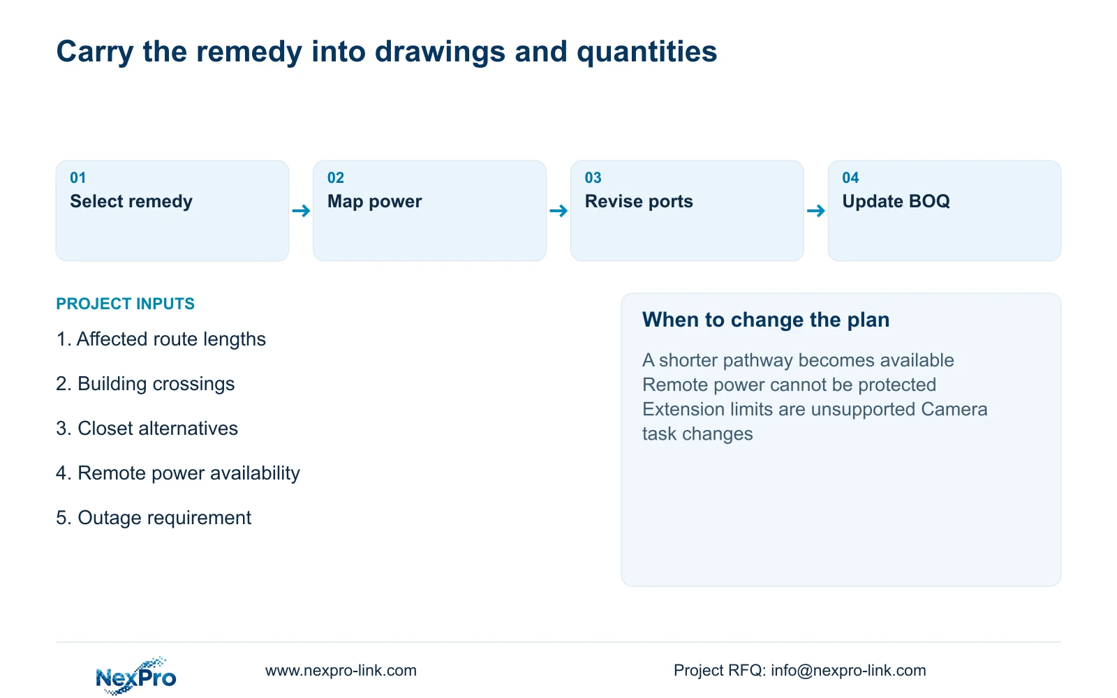
Issue a revised drawing that identifies the chosen remedy, copper segment lengths and active-node locations. Separate data connections from power protection. Update the port schedule and component list together, so procurement cannot buy a fiber interface while leaving the associated remote switch or supply outside the order.
Record what remains unchanged, including the camera’s observation task, recorder destination and required outage state. A remedy that restores link length while removing an agreed operating function needs a separate buyer decision. Installed-link testing and actual recording checks should follow the revised arrangement, with observations recorded against the final identities.
Send the affected route measurements, building boundaries, proposed closet locations and available remote power to info@nexpro-link.com. NexPro-Link can discuss equipment matching and coordinated supply through its hotel project and BOQ support scopes. Include the intended backup behavior and access restrictions. Local electrical and pathway work remains a defined project responsibility, not an automatic part of a coordinated equipment order.
| Situation | Required record | Decision boundary |
|---|---|---|
| Length is estimated | Drawing route and allowances | Survey before final release |
| Length is surveyed | Actual continuous route | Revise design and affected quantities |
| Connection already installed | Approved test/design basis | Assess the actual link; preserve the exception |
Section 07
Buyer questions
Can a camera being online justify keeping a 98 m permanent route? A brief online check does not establish conformity with the chosen permanent-link design or complete operating task. Resolve the route against its specified basis, or document an explicitly supported alternative and its testing requirements.
Is a remote switch covered by the recorder’s UPS? Only if the actual power design supplies and protects that remote switch. A network or fiber connection to the recorder does not establish a protected-power connection.
What information allows a useful first remedy quotation? Provide the affected fixed lengths, building crossings, possible closet positions and available remote power. Add the camera task and required outage state so alternatives preserve the same service.
Engineering references
These sources support the general planning principles. Always use the selected product's current datasheet and applicable project standards for final design.