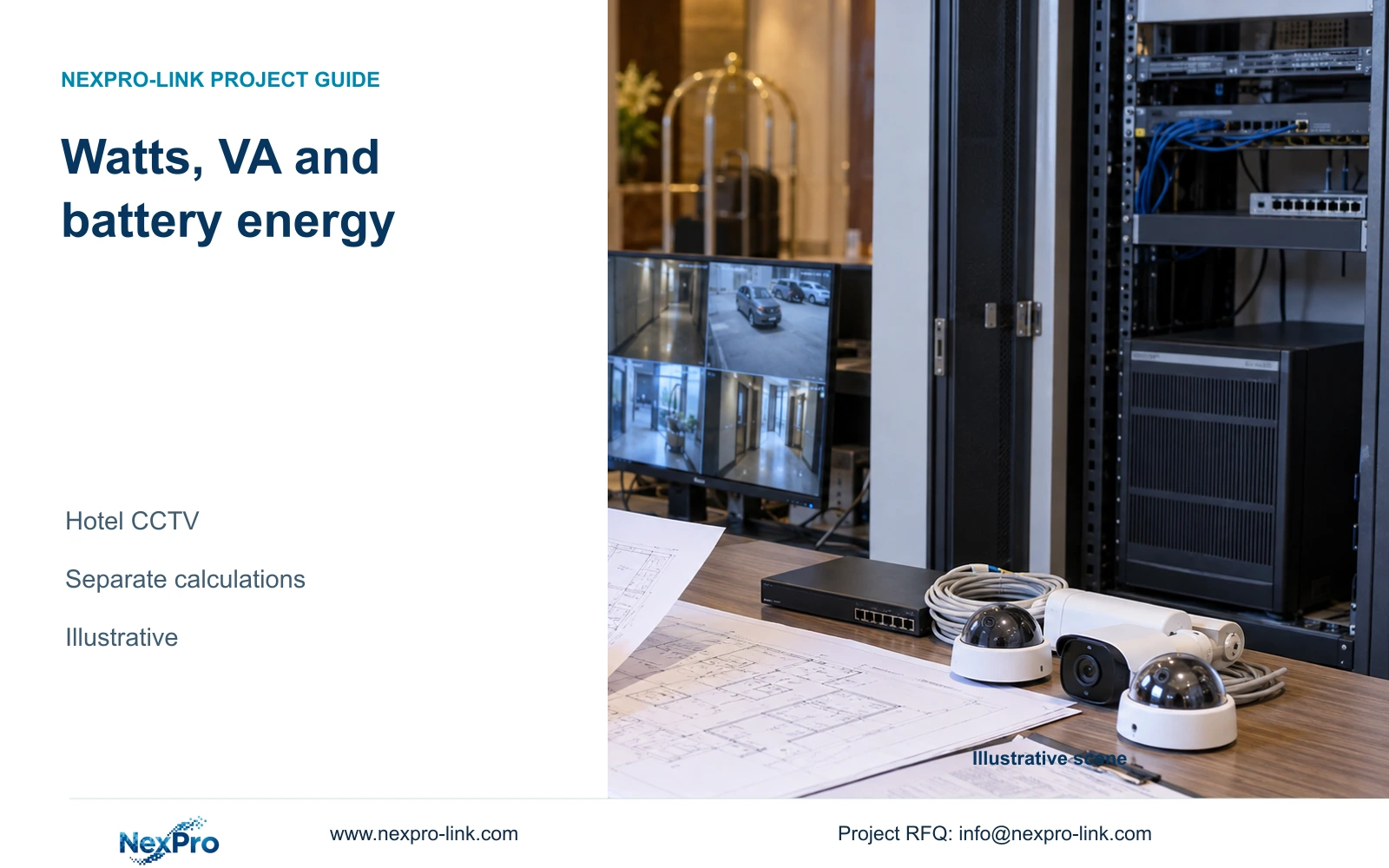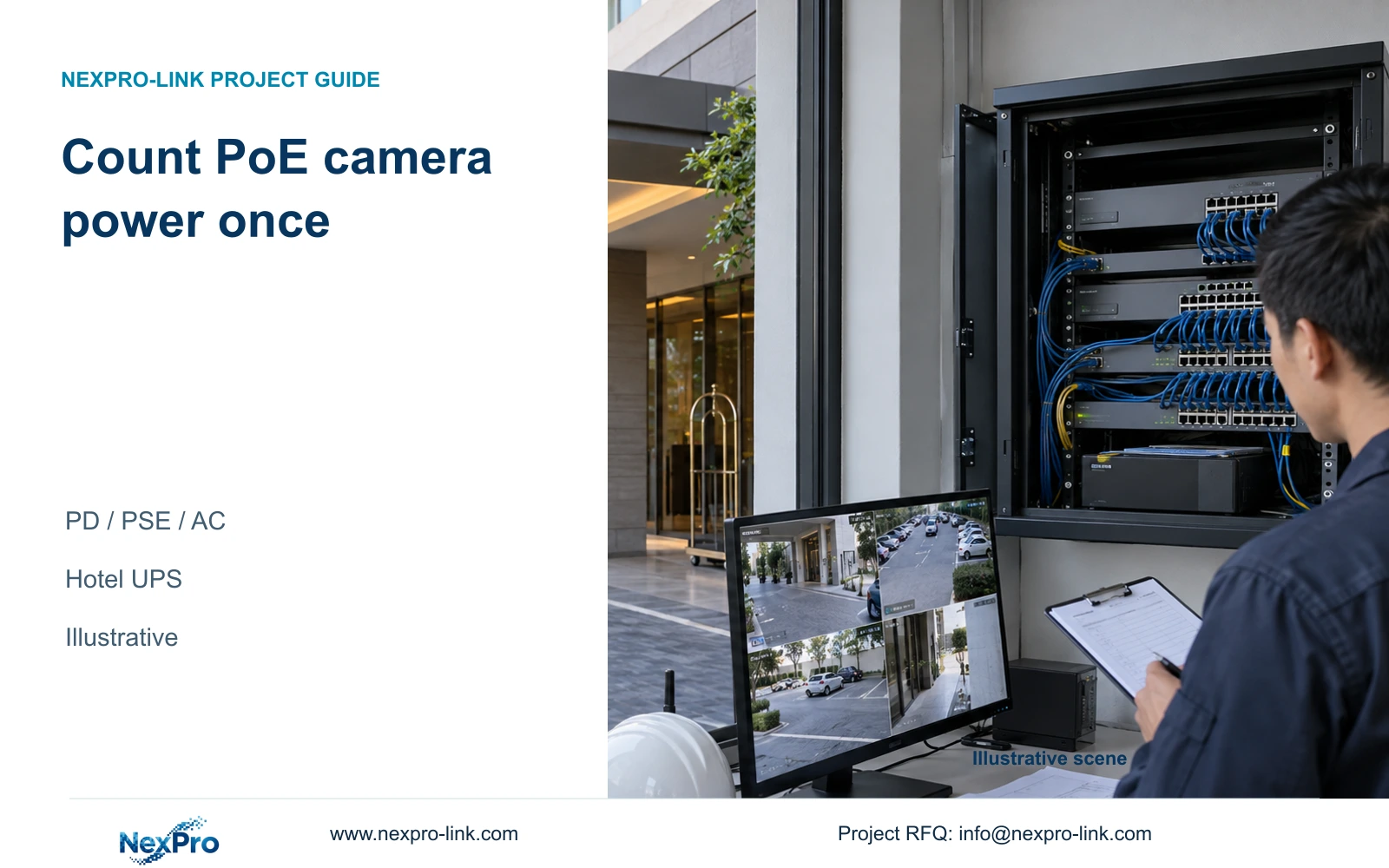
Complete switch AC consumption includes its connected PoE cameras under the measured condition. Use that boundary or estimate camera power with losses, but do not add both.
Section 01
Choose between camera PD values and complete switch AC input
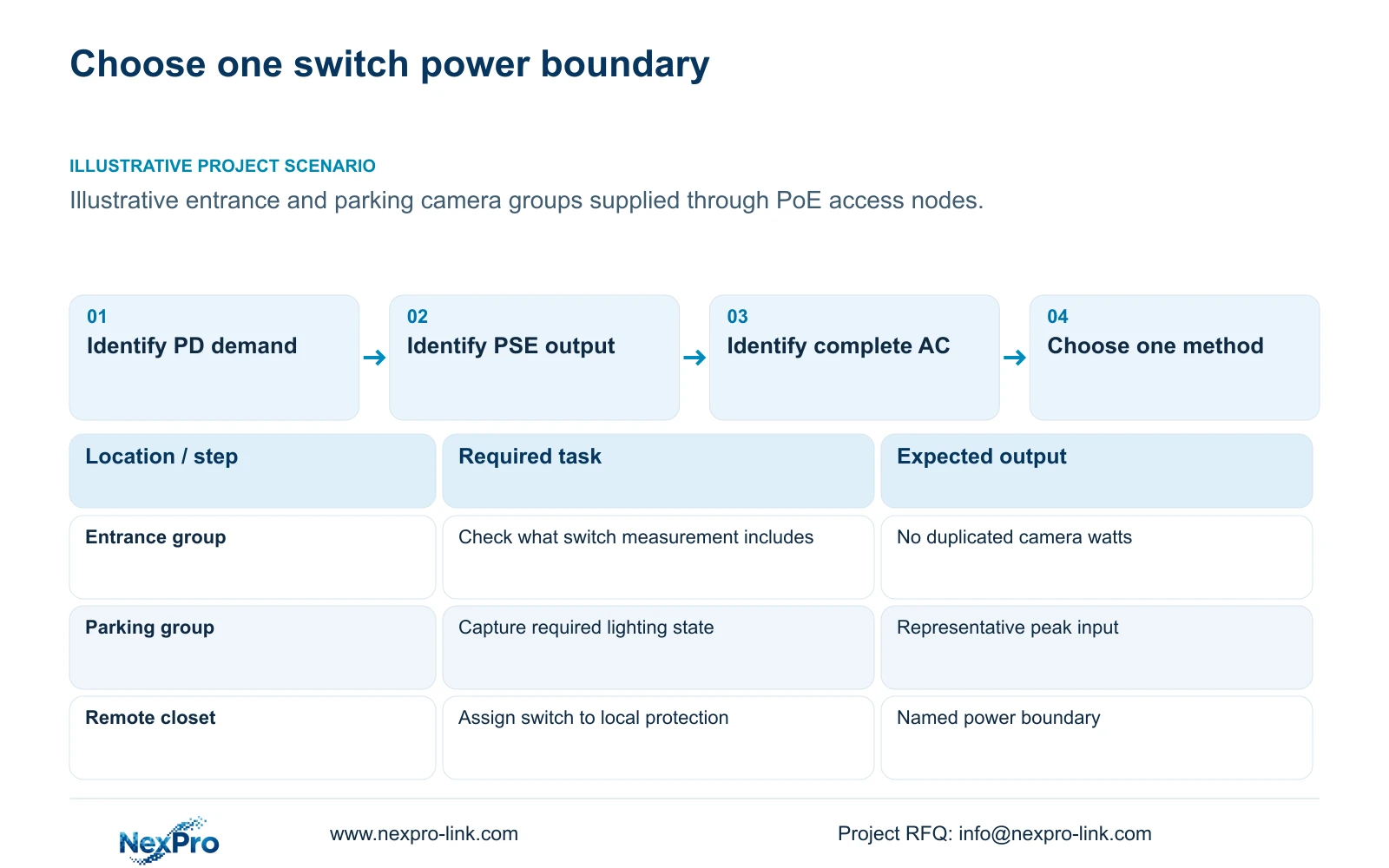
Use complete switch AC consumption when it covers the connected cameras and the required operating condition. Do not add those cameras again. When that measurement is unavailable, calculate camera PD demand through cable and conversion losses, then add the switch's own consumption once. A switch label needs interpretation before either method can be selected.
PD is the powered device boundary at the camera. PSE is the power sourcing equipment output at the switch. The AC input is upstream of both and includes the switch's conversion and internal consumption. A maximum PoE output budget, an AC power supply rating and a measured operating input describe different quantities.
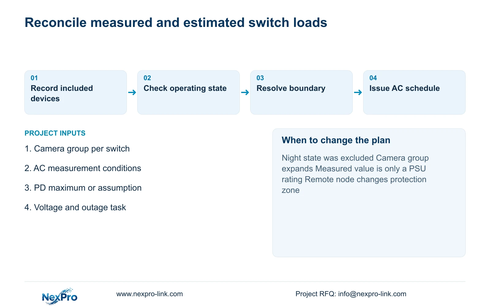
For a hotel entrance or parking camera group, identify which cameras were connected during measurement and whether their relevant lighting functions were operating. Mark values as measured, maximum or assumed. An observed low daytime input cannot automatically represent the approved night load, and a PSU rating cannot be presented as an observed load.
| Required task | Given information | Decision still needed |
|---|---|---|
| Size switch PoE output | Camera PD demand | Cable allowance and per-port capability |
| Size UPS load | Complete switch AC measurement | Connected devices and operating state |
| Estimate before installation | Camera demand and loss assumptions | Switch conversion and own consumption |
Section 02
Apply cable and conversion losses at their own boundaries
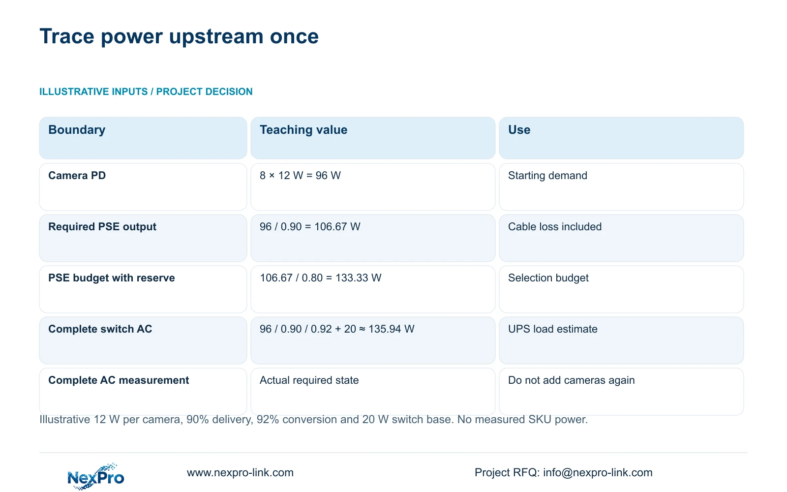
The supplied reference uses eight hypothetical cameras at 12 W PD peak each. Their combined camera demand is 96 W. With an assumed 90% delivery efficiency, the switch must supply 96 / 0.90 = 106.67 W at its PSE output. The 12 W value is a teaching input; the supplied camera PDFs do not establish that maximum.
Move upstream again using the assumed 92% PoE conversion efficiency. The camera-related AC contribution is approximately 106.67 / 0.92 W. Add the switch's own AC consumption separately to obtain its complete estimated input. Applying one unexplained multiplier to all equipment would obscure which losses have already been included.
The reference also retains 20% spare PSE output, giving 106.67 / 0.80 = 133.33 W as the required usable output budget. That budget is a selection requirement, not the actual AC consumption. Keep port availability and per-port power checks separate from the total output budget.
Section 03
Add the switch's own consumption once
For the same reference group, assumed switch consumption is 20 W. The bottom-up estimate is therefore (96 / 0.90 / 0.92) + 20 = approximately 135.94 W AC per node. The internal contribution occurs once per switch, regardless of how many individual camera rows appear in the schedule.
Four such reference nodes total 543.77 W when calculated before rounding the individual entries. This is the supplied case's aggregate switch estimate, not a measured hotel result. It must not be relabeled as the separate 750 W UPS example or supplemented with another copy of the same camera load.
If a complete switch AC measurement is used instead, its own consumption and downstream camera contribution are already represented. A schedule that combines complete AC input, the PD total and another base allowance repeats energy. Correct the boundaries before buying a larger UPS to accommodate that artificial increase.
| Method | Included scope | Do not add again |
|---|---|---|
| Complete AC measurement | Switch and connected cameras in the recorded state | Camera PD power and switch base |
| Bottom-up estimate | (96 / 0.90 / 0.92) + 20 ≈ 135.94 W | A second complete switch AC figure |
Section 04
Compare valid load methods before selecting UPS capacity
Use the two methods as alternatives for a particular switch, or as a reconciliation check when both are available. Differences should lead to examination of camera state, assumptions and included devices. They do not justify averaging incompatible boundaries. Mixed schedules are acceptable when each equipment row has a clear, non-overlapping scope.
After correcting the load list, check the UPS in watts and VA. The independent capacity example assumes 750 W AC and aggregate PF 0.9, producing 833.33 VA. Utilization equals load divided by the corresponding W or VA rating. These inputs are independent of the four-node reference total.
SP1KR(S) exceeds both steady-load figures but retains less than the example's 20% reserve. SP2KR(S) retains that reserve. Double counting would distort this selection and its battery estimate. Neither the corrected arithmetic nor the larger model's rating establishes backup minutes; obtain the load-matched battery curve.
| Metric / condition | SP1KR(S) | SP2KR(S) |
|---|---|---|
| Published rating | 1 kVA / 900 W | 2 kVA / 1800 W |
| Assumed protected load | 750 W / 833.33 VA | 750 W / 833.33 VA |
| W utilization | 83.33% | 41.67% |
| VA utilization | 83.33% | 41.67% |
| 20% W and VA reserve | Not retained | Retained |
| Battery runtime | Configured load curve required | Configured load curve required |
Section 05
Include equipment outside the PoE group
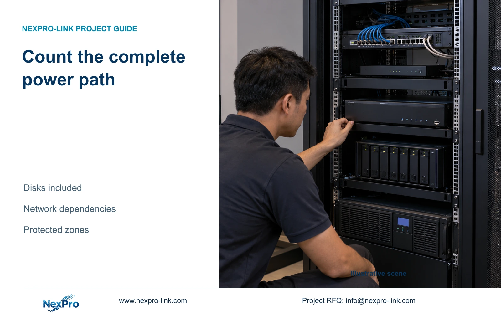
List the recorder with its disks, required core equipment and any approved operator devices outside the switch AC entries. Include a remote active node where recording depends on it. Assign that node to its local protection arrangement; a central rack total does not establish power distribution to another floor.
In the supplied case, recorder consumption of 60 W and core network consumption of 25 W are teaching assumptions. A 35 W ordinary monitor is separately identified. Optional wall and decoder loads require an explicit outage decision. Equipment supplied by the switch belongs inside its complete AC entry; independently supplied equipment needs its own row.
NexPro SW-POE1618G remains an inquiry candidate. The supplied page record has conflicting access-port speed descriptions and no numerical total PoE budget. Do not declare it compliant with the 133.33 W requirement. Ask for the exact output budget and port specification while keeping actual AC consumption a separate procurement input.
Section 06
Make the power boundary visible in the RFQ
Publish each switch entry with its location, connected camera group, operating state and measurement boundary. Show losses only on estimated rows. Keep camera counts visible for traceability while identifying their power as included in the switch AC total. This lets the equipment schedule support both procurement and later load verification.
Prefer complete AC measurements when they represent the required configuration and operating state. Change to a documented bottom-up estimate when cameras are not installed, the sample excludes relevant peaks or a proposed expansion changes the connected group. Recheck both methods after a material configuration change.
Send info@nexpro-link.com the switch load entries, camera groups, voltage and required backup behavior. Include whether values represent AC input, PD demand or PSE budget. NexPro-Link can coordinate the equipment response through hotel project and BOQ support. Its CCTV manufacturing core and supporting equipment supply are distinct from local electrical installation and site testing.
Section 07
Buyer questions
Is a switch's maximum PoE budget its UPS load? No. It describes available output capacity. UPS planning needs the complete AC input for the required operating state, or a documented estimate including delivered camera demand, losses and the switch's own consumption.
Can a daytime measurement support the night-load quotation? Only if it represents the required night operating state. Otherwise request the relevant maximum or measure the configured lighting state. The supplied camera documents do not provide a verified maximum W value to fill that gap.
What service terms belong beside the corrected load schedule? Identify who supplies and installs the UPS, who verifies remote-node power and who performs the outage test. Equipment coordination does not automatically include local attendance or every third-party component.
Engineering references
These sources support the general planning principles. Always use the selected product's current datasheet and applicable project standards for final design.