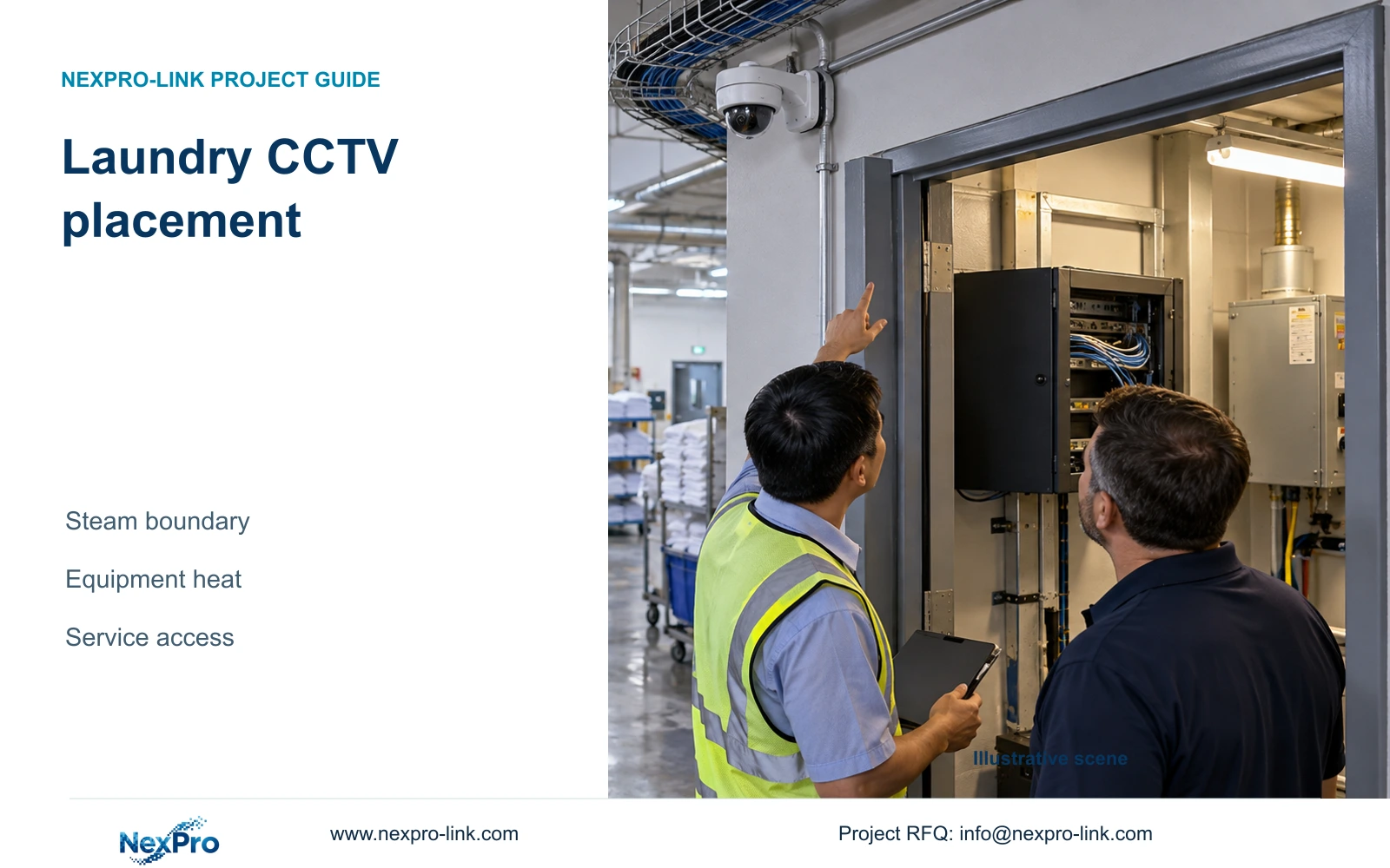
Laundry CCTV needs separate decisions for the viewing position and the equipment environment. Steam exposure, room heat and practical service access must all remain visible.
Section 01
Locate steam and heat before placing equipment
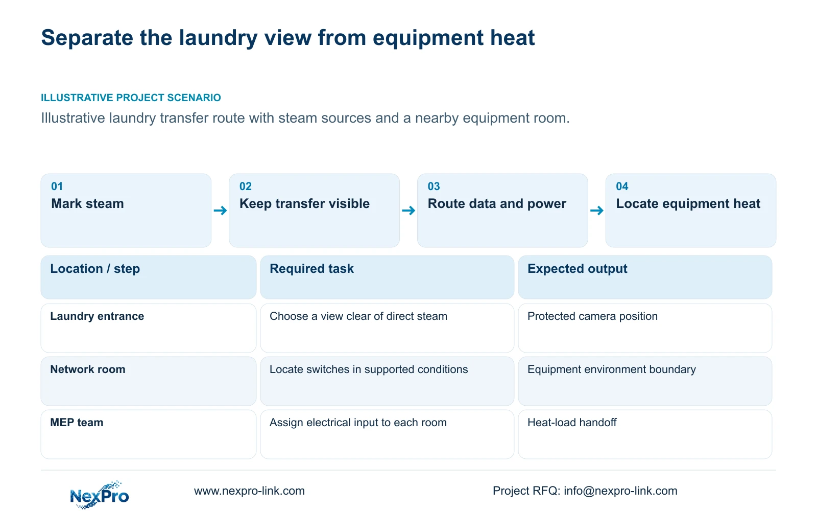
Place laundry cameras and connections away from direct steam, and put ordinary network and recording equipment in a suitable controlled environment wherever practical. Keep an exposed local node only when its equipment and installation conditions support the actual location. A laundry entrance view and a switch beside laundry machinery require separate environmental decisions.
Mark steam sources, hot equipment and the service route on the layout. Include operating and cleaning states, since a location that appears sheltered during an idle period may experience different exposure while work is underway. The camera body, mounting arrangement and cable termination each need a defined location. Do not infer their conditions from the room's average temperature alone.
Separate the environmental survey from equipment heat estimation. Camera selection needs the actual mounting conditions, while mechanical planning needs the electrical input and heat location of installed equipment. A W-to-BTU/h conversion can estimate equipment heat; it cannot describe moisture from laundry activity or establish the full room cooling requirement.
| Required task | Given information | Decision still needed |
|---|---|---|
| Observe linen transfer | Laundry entrance and route | View clear of direct steam |
| Locate network equipment | Available equipment spaces | Supported environment and cable route |
| Provide mechanical input | Proposed equipment schedule | Actual operating input and heat location |
Section 02
Choose the least exposed view
Start at the linen-transfer or access event that needs a record. A view from the service approach may capture the handoff without placing the camera above the steam source. Check whether doors, tall trolleys or stored items interrupt the action. If they do, compare another mounting position before expanding the camera count.
Keep the required target plane and recorded detail explicit. Moving a camera away from exposure changes its angle and view width, so environmental improvement alone does not establish equivalent footage. An overview can explain movement through the area while a closer view may be needed for a specific transfer. Combine those tasks only when both remain usable.
The supplied camera PDFs provide ordinary camera candidates with stated image and environmental fields, not laundry-specific exposure approval. Treat a published temperature range and IP field as separate information from steam, cleaning and connection requirements. Select specialist components if the necessary view cannot be obtained from a supported protected position.
| Item | Protected service approach | Exposed local position | Effect |
|---|---|---|---|
| View | Check angle and obstruction | Check angle and obstruction | Required action must remain visible |
| Environment | Reduced direct exposure sought | Specific exposure support needed | Changes equipment requirements |
| Access | Service route available | May require operational coordination | Changes maintenance scope |
Section 03
Separate camera and network environments
Draw the data route from the laundry camera to its switch and recorder, then identify the power route separately. A camera can remain near the required entrance while the switch sits in a suitable equipment room. This placement reduces the need to qualify ordinary network equipment for the laundry environment, provided the resulting link and access arrangements are acceptable.
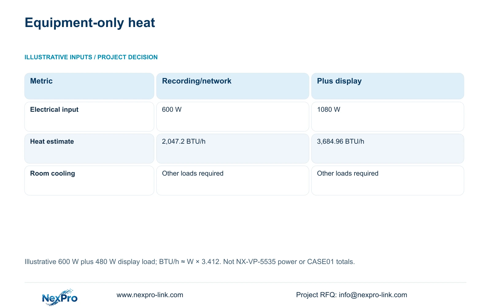
Use electrical input at a stated boundary when preparing mechanical information. For the independent illustration in this article, recording and network equipment are assumed to draw 600 W; optional display equipment adds 480 W. These are teaching inputs, not product measurements. Equipment heat estimate in BTU/h equals electrical input W multiplied by approximately 3.412. The conversion uses the International Table Btu, as listed in the NIST SI guide; it is a unit conversion, not a room-cooling specification.
Identify which loads release heat in each room. A PoE switch's electrical input includes power delivered onward, so a room-level heat schedule must distinguish local losses from energy used at remote equipment. Similarly, add UPS conversion loss without counting its downstream equipment input twice. The complete electrical boundary and physical locations should accompany the mechanical handoff.
Section 04
Compare enclosure and relocation options
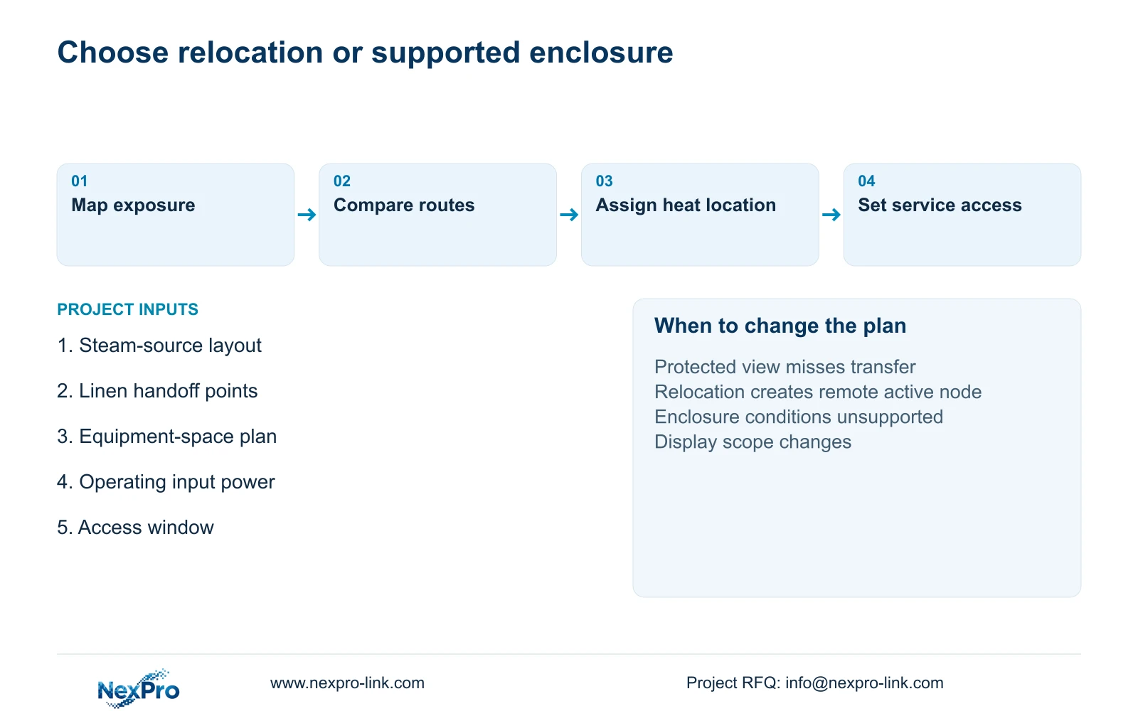
Prefer relocation to a suitable equipment area when it preserves the recording task and provides a practical route. An enclosure option needs a supported arrangement for its equipment, environment and heat rejection. A cabinet around ordinary equipment does not by itself establish suitable internal conditions or access for service.
Compare the full scope: route work, local power, terminations, enclosure requirements and maintenance responsibility. If relocation creates a remote active node, that node still needs its own supported environment and supply. Fiber can change the data route but does not automatically deliver power to the laundry endpoint. The outage requirement must cover every necessary active component.
Moving a display or recorder changes where its heat occurs. Removing an optional display from a protected-power list changes the UPS load, but its operating heat remains in the room where it is installed. Keep these consequences visible to the electrical and mechanical teams. CASE01's system totals are independent of this article's 600 W and 480 W assumptions.
| Retained outcome | Extra scope | When justified | Counter-condition |
|---|---|---|---|
| Laundry entrance recording | Route to controlled equipment room | Supported link and service access | Route creates unresolved dependencies |
| Necessary local node | Supported enclosure arrangement | Relocation cannot preserve task | Internal conditions remain unsupported |
| Operator viewing | Display in another suitable space | No laundry-local display task | Local viewing is explicitly required |
Section 05
Estimate equipment heat loads
The illustrative totals below compare recording/network equipment only with the same scope plus display equipment. Multiplying 600 W by 3.412 gives 2,047.2 BTU/h. Adding the assumed 480 W produces 1,080 W, or 3,684.96 BTU/h. The comparison shows how optional display scope changes the equipment-only planning input.
Use these figures to ask whether the proposed equipment location and airflow arrangement remain suitable after a display is added. They are not an air-conditioner selection. The mechanical designer must consider other room loads, moisture, outside conditions and the intended operating or redundancy strategy. Laundry process loads are not included in this small equipment illustration.
NX-VP-5535 is a 55-inch LCD with a listed 1920×1080 resolution; the 480 W assumption is not its measured or nameplate power. SP2KR(S) has a published 2 kVA/1800 W rating, but that rating supplies neither a UPS loss figure nor battery runtime. Request actual selected-configuration inputs before replacing the teaching schedule with procurement data.
| Metric / condition | Recording and network only | Same equipment plus display |
|---|---|---|
| Equipment electrical input (W) | 600 | 1080 |
| Equipment heat estimate (BTU/h) | 2,047.2 | 3,684.96 |
| Room cooling design | Additional room loads required | Additional room loads required |
Section 06
Assign cleaning and maintenance access
Give the hotel a named responsibility for optical-surface cleaning and a separate technical route for connections, switches and recorder faults. Identify access restrictions and the operating window for service. Recheck the recorded view after cleaning or adjustment so a completed maintenance visit does not conceal a changed camera angle.
Recommend the least exposed position that preserves the approved linen-transfer task, with network equipment in a suitable controlled space. Change to a documented specialist arrangement if relocation loses the necessary view or link, or if actual environmental conditions exceed the selected equipment's support. Recalculate mechanical inputs when displays, power equipment or device quantities change.
Send the laundry layout with steam sources and handoff points, proposed equipment-space location, available power information and service-access limits to info@nexpro-link.com. NexPro-Link can discuss coordinated equipment and BOQ documentation. Local mechanical design and installation remain separately assigned. The supplied policy records a receipt-based 24-month limited hardware baseline for applicable main equipment; accessories and project service costs require their written scope.
Section 07
Buyer questions
Can the heat table be used to select laundry air conditioning? No. It is an equipment-only illustration. Give the mechanical designer the actual equipment input, locations and operating states along with the laundry's other room and moisture loads.
Does a larger UPS solve a hot equipment location? UPS capacity addresses electrical load limits. It does not establish a suitable environment or cooling arrangement. Its losses also need to be located correctly in the room heat schedule.
Can relocation be compared before final equipment selection? Yes. Compare routes, available spaces and service responsibility using clearly provisional inputs. Replace those assumptions with the selected device dimensions, environmental conditions and electrical inputs before finalizing the equipment arrangement.
Engineering references
These sources support the general planning principles. Always use the selected product's current datasheet and applicable project standards for final design.