An illuminated NVR cannot prove outage recording. Commission every required camera and network power zone, then verify retained footage and recovery.
Section 01
Choose the recording path that must survive
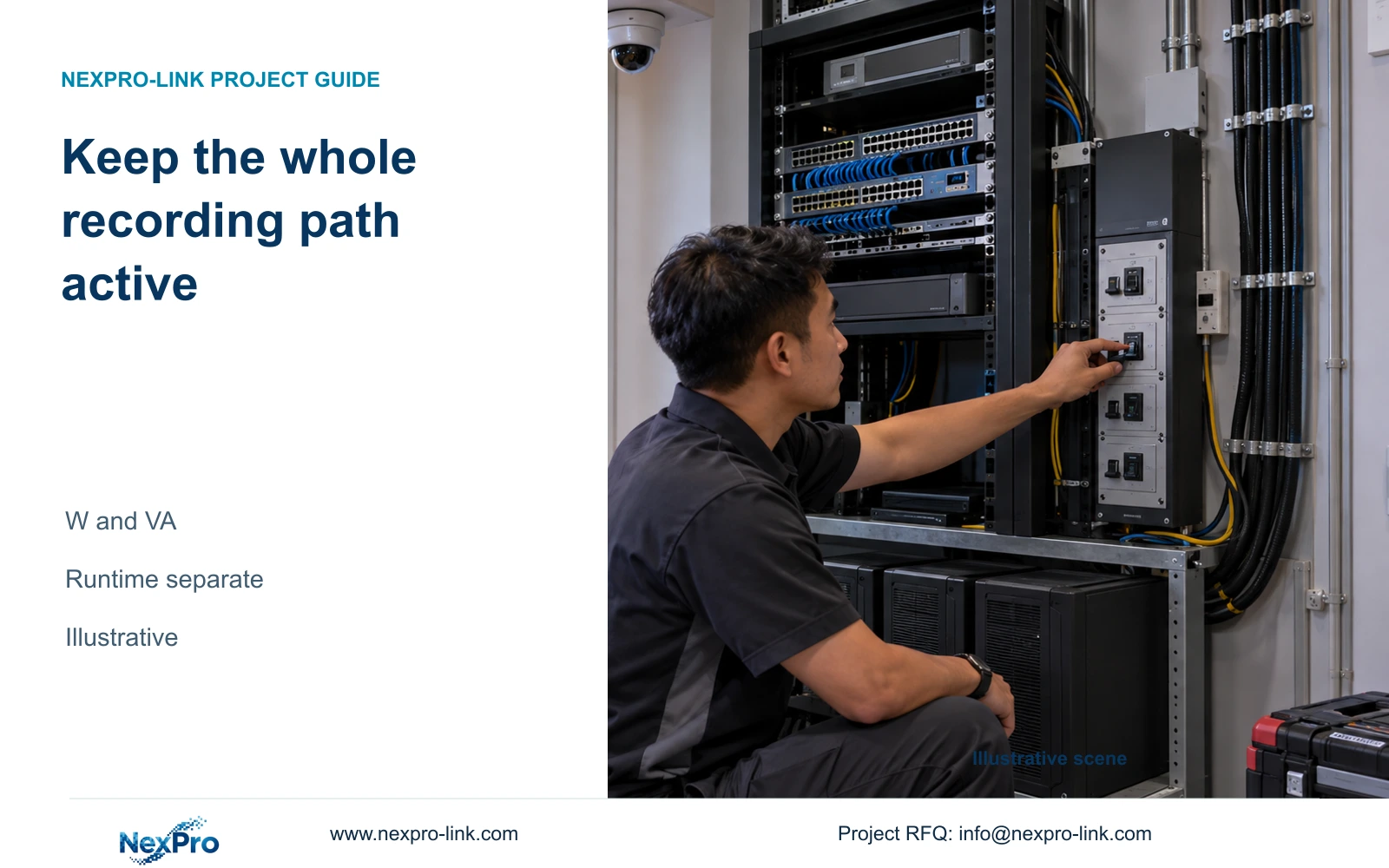
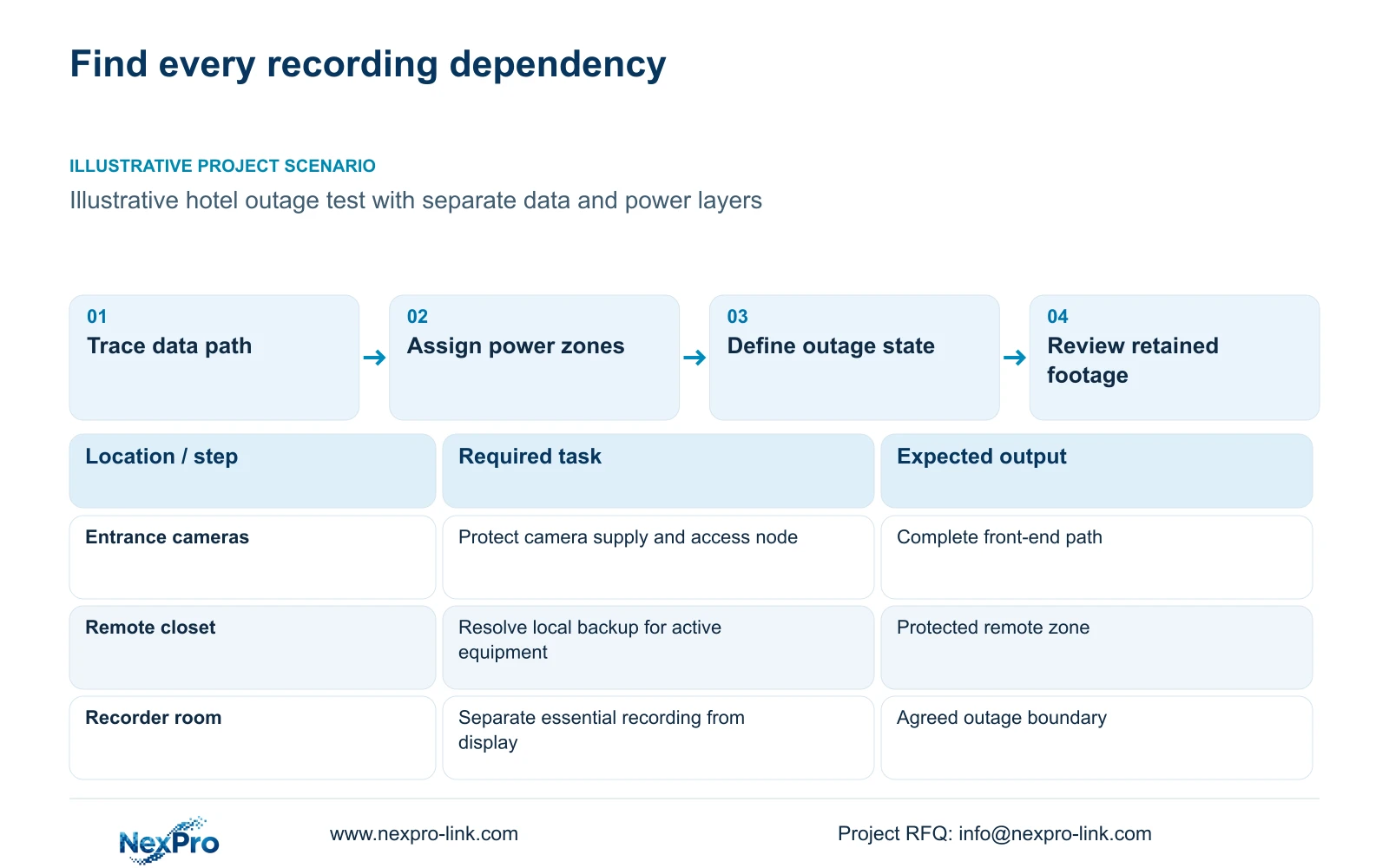
Commission the complete protected recording path when the hotel requires recording during an outage. Include camera supply, access switches, required backbone nodes and the recorder. If any essential remote node loses power, correct that protection boundary before accepting the system, even when the NVR remains illuminated.
Draw data and power paths separately. The data drawing shows how camera streams reach storage and authorized clients. The power drawing identifies the supply serving every required active component. Fibre can maintain a data connection only while its active endpoints operate; it does not provide power to a remote switch.
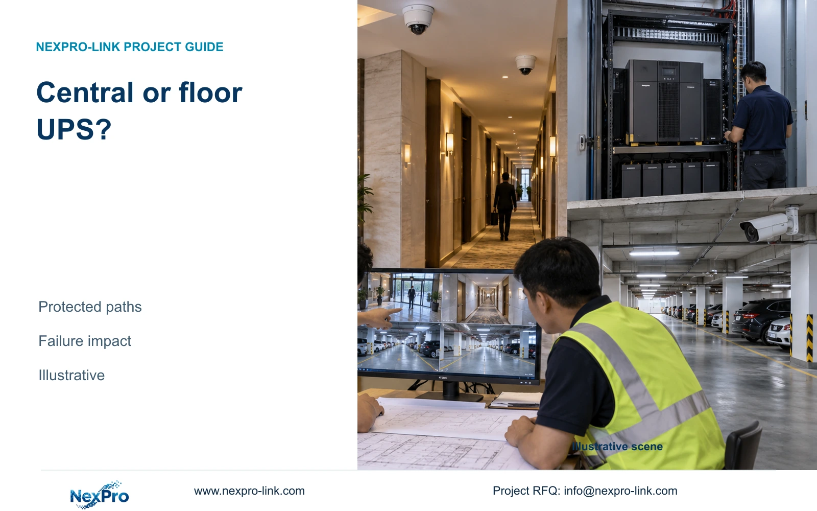
Define the outage service explicitly. The hotel may require all scheduled recording while treating a larger control-room display as optional. Keep that distinction visible during commissioning. A distributed hotel needs resolved protection in each relevant closet or building; an aggregate load calculation does not establish that one central UPS supplies every location.
| Required task | Given information | Decision still needed |
|---|---|---|
| Retain entrance recording | Camera depends on PoE access and recorder | Confirm protection of every active node |
| Continue remote-zone recording | Backbone includes remote equipment | Resolve local supply and backup |
| Maintain operator display | Display may be optional | State whether it belongs in the protected load |
Section 02
Measure the agreed load state
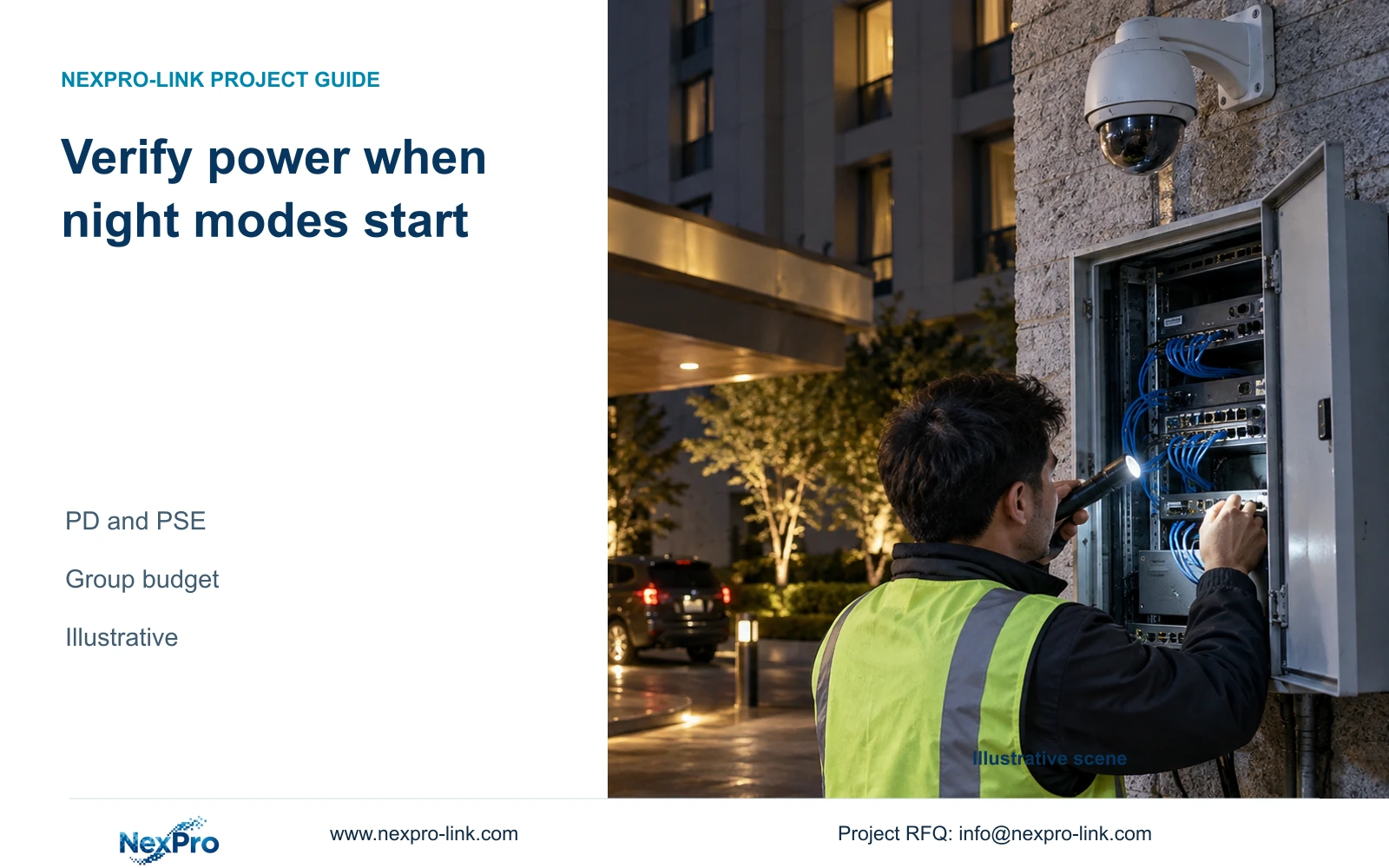
Prepare a load schedule in watts and VA for the actual outage state. Label nameplate maxima, typical figures and measured values distinctly. Include the selected camera modes and any operator equipment that must continue. A daytime measurement with illumination inactive may not represent the required night condition.
Use consistent AC boundaries. Complete PoE switch AC input includes its downstream camera contribution, so those cameras must not be added again. List the recorder, core network and selected displays separately. When a value is estimated, retain the assumptions that connect device demand to switch AC input.
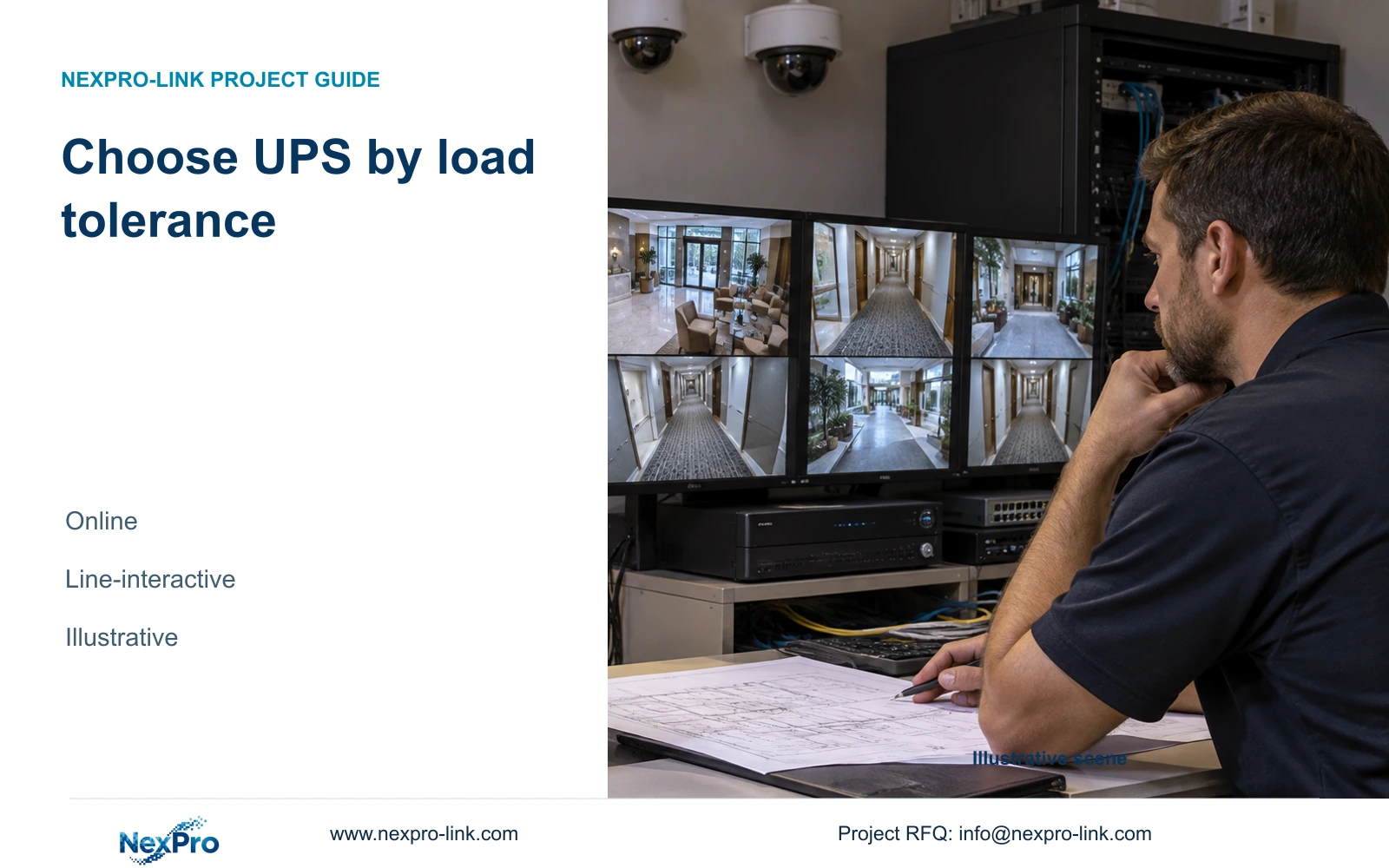
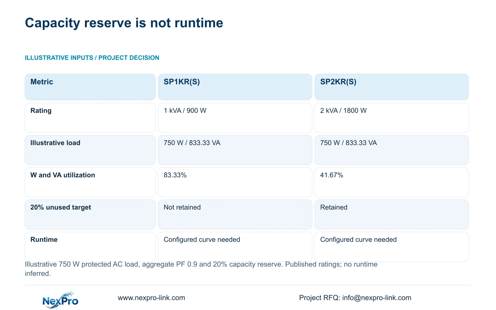
Compare both W and VA with the exact UPS ratings. SP1KR(S) is rated 1 kVA/900 W, while SP2KR(S) is 2 kVA/1800 W. These rack models are online double-conversion LiFePO4 candidates. SP2K(S), the tower model, is 2 kVA/2000 W and is a different configuration; matching kVA does not make the watt ratings interchangeable.
Section 03
Calculate capacity and the energy envelope separately
The illustrative protected AC load is 750 W with aggregate power factor 0.9. Load VA equals W divided by power factor, giving 833.33 VA. W utilization equals load W divided by rated W; VA utilization uses the corresponding apparent-power ratings. These inputs are independent of the complete hotel reference case.
SP1KR(S) operates at 83.33% of both ratings under this example, while SP2KR(S) operates at 41.67%. Both exceed the steady load, but only SP2KR(S) retains the stated 20% unused W and VA target. Recommend it as the capacity candidate under those conditions, subject to the actual installation and supported battery configuration.
Energy is a separate calculation. Output energy in Wh equals load W multiplied by required minutes divided by 60. Battery planning must also address conversion efficiency and usable energy, while the actual runtime requires the configured load curve. No duration is assigned here, and neither the capacity table nor a default battery figure establishes minutes for the selected model.
| Metric / condition | SP1KR(S) | SP2KR(S) |
|---|---|---|
| Model rating | 1 kVA / 900 W | 2 kVA / 1800 W |
| Protected load (W / VA) | 750 / 833.33 | 750 / 833.33 |
| W utilization | 83.33% | 41.67% |
| VA utilization | 83.33% | 41.67% |
| 20% W & VA reserve target | Does not retain target reserve | Retains capacity reserve |
| Battery runtime | Need the configured load curve | Need the configured load curve |
Section 04
Test transfer and recovery safely
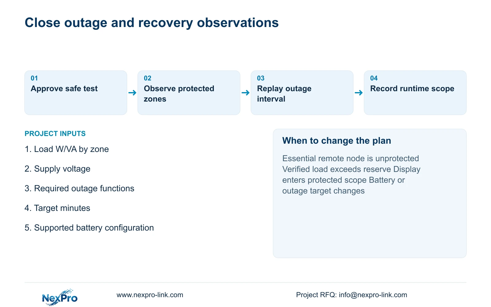
Have the appropriate electrical professionals plan and supervise the site interruption and recovery test. Define the protected zone, required service and approved operating sequence before the test. Electrical protection, grounding and changeover arrangements require site-specific professional scope; a system relationship diagram is not an installation instruction.
Observe the selected camera and network groups during the approved transfer. Record the relevant equipment state and any loss of the required task. Factory demonstrations support their reproducible setup, but they do not establish the hotel's installed power distribution, remote-node behavior or recovery sequence.
After supply restoration, verify the agreed recovery workflow and retain any unresolved observations. If a correction changes the load or protection boundary, repeat the affected sequence under comparable conditions. A brief successful transfer does not establish the full target runtime, battery life or operation under every possible load state.
Section 05
Check recording continuity and timestamps
Review the footage retained across the test interval for each required group. Confirm that the recorded sequence and displayed timestamps allow the operator to follow the agreed event. A live image after restoration cannot establish what was retained during the interruption. Use the required retrieval workflow to expose missing intervals or unavailable views.
Include distributed paths in this review. A central recorder can remain active while a floor access node stops delivering streams. Compare the observed loss with the protection drawing to identify the missing dependency. A remote client becoming unavailable is also a different outcome from loss of local recording, so describe both precisely.
Keep optional display protection separate from essential recording. Adding ordinary monitors or a wall changes protected load and can alter runtime. Buy that extra scope when continued display operation is an approved task, then revise the load and battery proposal. If the hotel only requires recording continuity, leave the optional display outside the claimed outage service.
| Retained outcome | Extra scope | When it is worth buying | Counter-condition |
|---|---|---|---|
| Required remote recording | Remote-node protection | An essential node otherwise loses supply | Central capacity alone does not resolve distribution |
| Continued operator display | Display backup | Hotel requires viewing during the outage | Optional display reduces recording runtime margin |
Section 06
Document measured runtime conditions separately
Present the planning estimate, supplier load curve and site observation as distinct evidence. Record the exact battery configuration, load state and relevant environmental conditions associated with a runtime observation. A partial-duration test should remain a partial observation; it cannot establish an unobserved longer interval.
For the 750 W, PF 0.9 example with 20% capacity reserve, SP2KR(S) is the supported capacity candidate. Change the proposal when verified load, power factor or distributed protection differs. Extend runtime through an explicitly supported battery configuration when necessary, rather than assuming a larger kVA label supplies more usable energy. Do not transfer another model's default Wh value to SP2KR(S).
Send the W/VA load schedule by power zone, voltage, required outage behavior and runtime target to info@nexpro-link.com. NexPro-Link can discuss a scoped equipment proposal through hotel project or BOQ support. The supplied policy gives applicable main equipment a 24-month limited hardware baseline from receipt; batteries and other categories follow their written scope. Remote technical support does not establish included local electrical work or free site attendance.
Section 07
Buyer questions
Can the smaller rack UPS meet this example without the reserve target? Its 900 W and 1000 VA ratings exceed the illustrative 750 W and 833.33 VA steady load. It does not retain the stated 20% reserve. Actual selection still requires the relevant load behavior, battery configuration and installation scope.
Does a successful transfer prove the required runtime? No. Transfer observation and duration verification address different conditions. Retain the configured battery curve and the actual test duration, load and environment. Do not extend a brief observation into an untested runtime promise.
What if the NVR records locally but remote viewing fails? Compare that result with the approved outage service. If remote viewing is required, its network dependencies need protection and testing. If it is optional, document the limitation while separately verifying local recording and retrieval.
Engineering references
These sources support the general planning principles. Always use the selected product's current datasheet and applicable project standards for final design.