Assign video traffic only to the links it crosses. A segment-by-segment matrix exposes genuine core bottlenecks without placing the whole hotel's recording and viewing total on every cable.
Section 01
Draw the recording path before sizing the core
Size each core link from the streams that actually traverse it, including the approved simultaneous operating tasks and an explicit allowance. Do not assign the hotel's complete recording and viewing total to every segment. Retain the simpler qualifying topology unless calculated demand, failure-state operation or a mandatory network requirement calls for a different arrangement.
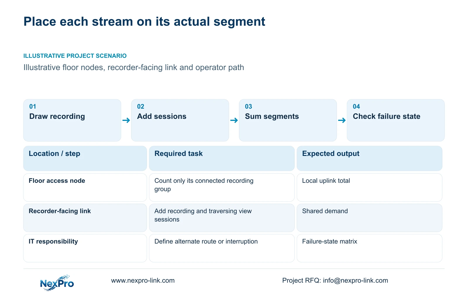
Begin with cameras grouped by their actual access node and recorder destination. Give each segment an identity so the same path can be discussed in drawings, quotations and testing. Show whether recording crosses the core or remains within a local group. A total camera count provides context, but it cannot explain where traffic accumulates.
CASE01 illustrates four groups of eight cameras feeding a recorder. At its assumed 4 Mbps per camera, each group generates 32 Mbps and the recording aggregate is 128 Mbps. That reference does not establish the routes for another hotel. Use actual group assignments and keep the separate power diagram available, because a correctly sized link cannot maintain service through an unprotected active node.
| Task | Path to identify | Sizing consequence |
|---|---|---|
| Continuous recording | Camera group to recorder | Sum each stream on its traversed segments |
| Local viewing | Actual source to operator client | Add only on shared viewing segments |
| Remote retrieval | Recorder to approved destination | Identify additional egress demand |
Section 02
Add live viewing and replay as separate sessions
Describe the operator workload before adding rates. A routine grid, an incident detail view and recorded playback are different sessions. Identify how many can run together and where their video originates. An operator session supplied by the recorder does not follow the same route as a direct camera connection.
Keep main recording unchanged while comparing viewing layouts. Substreams may meet a routine overview task with less traffic, while an event view may need a main stream. Replay and export should have their own rows with approved concurrency. Do not assume a viewing allowance includes every incident operation simply because all use the same workstation.
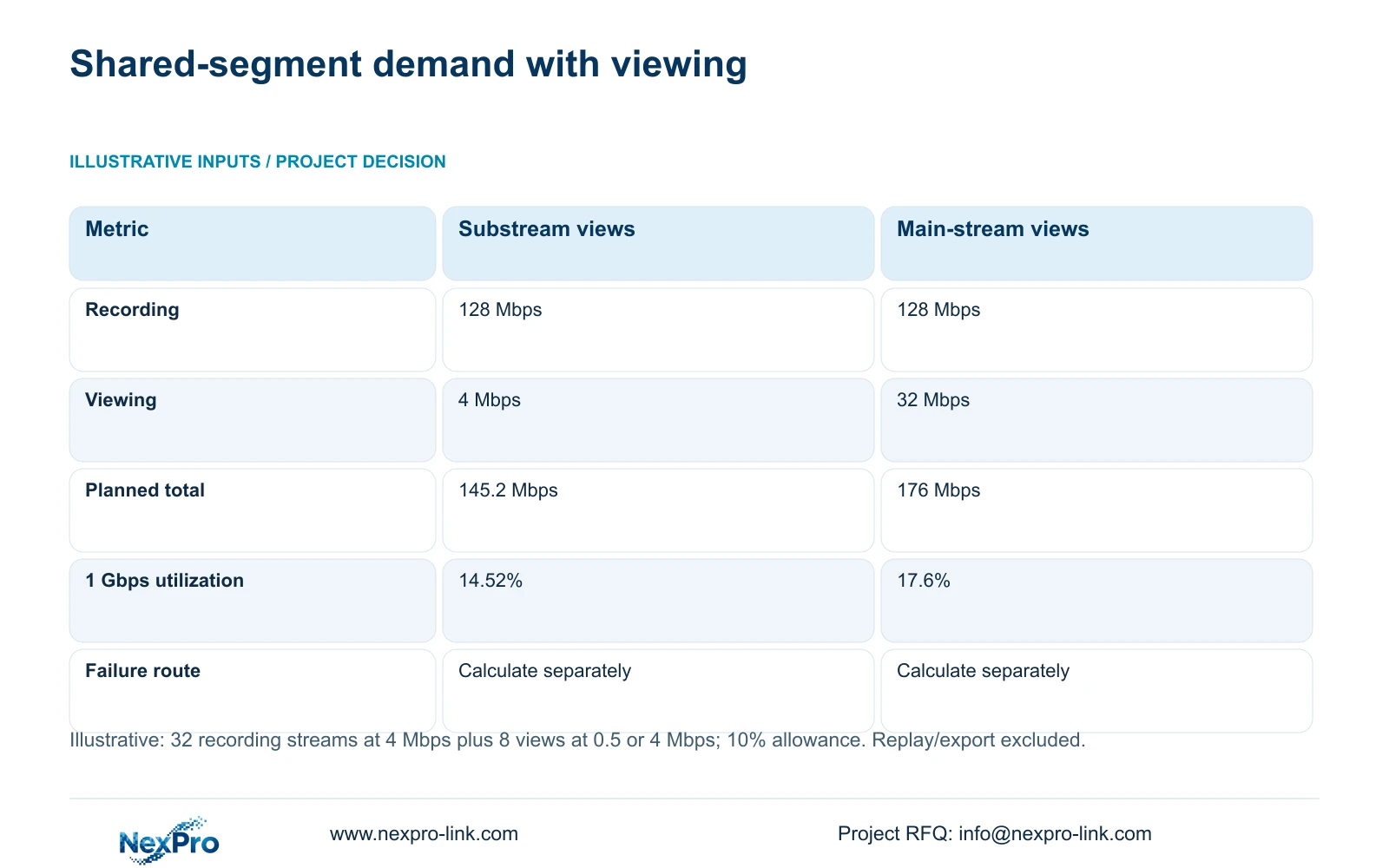
The shared-link example below includes eight live views only. It provides a controlled comparison between 0.5 Mbps substreams and 4 Mbps main streams. Playback, exports and unrelated hotel IT traffic are outside its numeric result. Where those activities share a proposed core segment, add their actual planning inputs before accepting the link.
Section 03
Calculate the demand on the identified shared segment
This illustration deliberately groups 32 recording streams and eight viewing streams on one shared link. Recording contributes 128 Mbps, and viewing contributes 4 or 32 Mbps. The 145.2/176 Mbps figures represent one-direction demand only if all those flows traverse that direction together. With full-duplex Ethernet, keep opposing directions separate, as Cisco's generic explanation of simultaneous sending and receiving makes clear.
The resulting demands are 145.2 Mbps and 176 Mbps. With 1 Gbps treated as 1,000 Mbps, nominal utilization is 14.52% or 17.6%. The 10% addition is a teaching allowance, not a measured network-overhead value. These averages support planning but do not establish burst performance or the forwarding capability of a selected switch.
Apply the same method to every other segment using its own streams. In CASE01, a recording-only eight-camera uplink has a separate 35.2 Mbps planning result after the same allowance. Copying 176 Mbps onto that link would charge it for traffic it does not carry. Conversely, omitting actual shared replay traffic can understate a busy recorder-facing segment.
| Metric / condition | Eight substream views | Eight main-stream views |
|---|---|---|
| Recording traffic (Mbps) | 128 | 128 |
| Viewing traffic (Mbps) | 4 | 32 |
| Planned link traffic (Mbps) | 145.2 | 176 |
| 1 Gbps nominal utilization | 14.52% | 17.6% |
| Other links | Calculate their own flows | Do not copy this sum to every segment |
Section 04
Compare normal routing with the agreed failure state
A normal-state matrix should name the active routes. A failure-state matrix should explain what happens when a specified link or node is unavailable. If supported alternate routing carries the affected traffic elsewhere, calculate that new shared demand. If service stops, describe the interruption boundary instead of assuming spare bandwidth provides automatic recovery.
Two physical network sockets do not establish failover or combined capacity. The supplied NexPro-NVR4449-4K record lists dual Gigabit interfaces and 320 Mbps input, but those facts do not prove a particular redundancy mode. Its recording and playback modes also need configuration-specific checks. The network proposal must state the mechanism on which continued operation depends.
Include the recovery task and responsible party. A spare switch may support restoration after replacement and configuration; it does not create an uninterrupted alternate path. If local stock is proposed, check functional substitution and retained version records. Do not use unspecified failure probabilities to justify a larger core or describe an untested arrangement as resilient.
Section 05
Buy faster uplinks where the operating matrix requires them
The illustrated 145.2 Mbps and 176 Mbps demands provide no bandwidth-planning reason to select 10 Gbps for that segment. A faster uplink becomes relevant when the actual shared workload, approved growth or required failure-state routing cannot fit the chosen capacity basis. Preserve the same recording and viewing outcomes when comparing alternatives.
Separate link rate from switch forwarding, recorder ingestion and client decoding. Faster links cannot correct an unsupported recorder mode or operator decode layout. Expansion also needs exact interface and equipment compatibility inputs. Price the incremental devices, connections and configuration work as a defined scope rather than assigning an unexplained upgrade allowance.
NexPro SW-POE1618G remains a possible access-device inquiry candidate, not an established core solution. Its source title and detailed access-speed table conflict, and total PoE watts are missing. Request the exact port revision and output budget. A Cat6 patch panel such as SP5648 identifies a cabling component; it does not establish the complete channel or switch performance.
Section 06
Issue a traffic matrix with a clear operating boundary
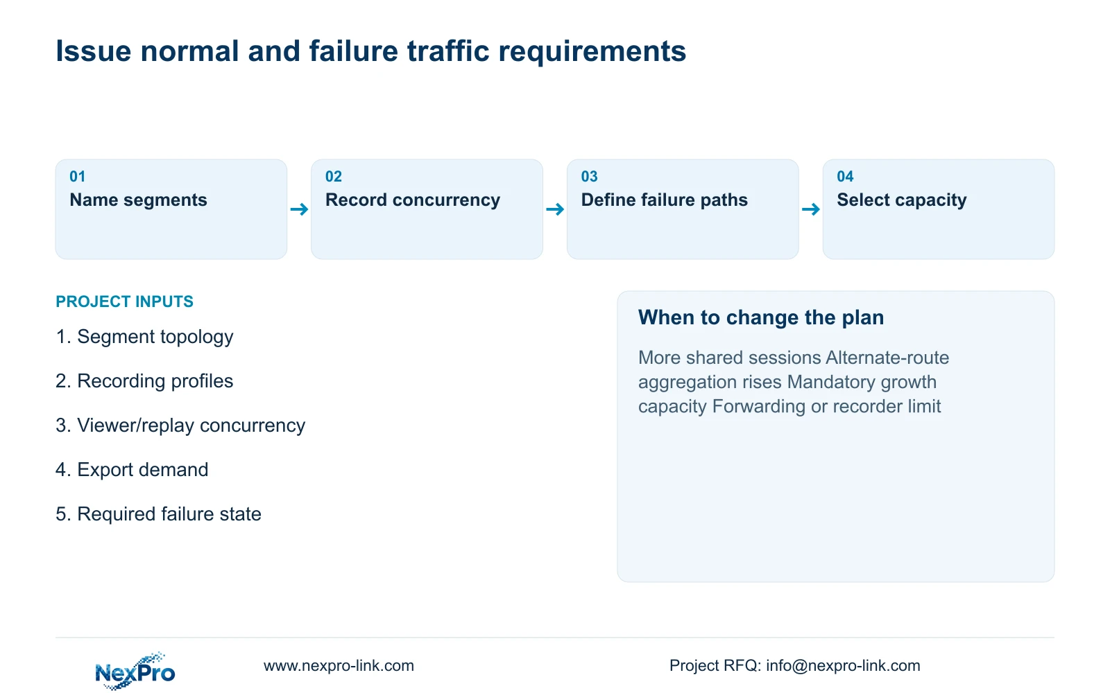
For each segment, record its endpoints, direction, stream group, concurrent sessions, allowance and nominal interface rate. Add the relevant failure-state route or service interruption. Distinguish known profiles from assumptions so the next design revision can replace a value without changing the accounting method.
Give the cost manager the matrix alongside the equipment schedule. That allows a quotation to explain why one link is Gigabit and another needs more capacity, while exposing missing viewing or export scope. Record any retained equipment and proposed deviations. The recommended topology should meet both the agreed normal workload and the explicitly required failure condition.
Send info@nexpro-link.com the topology, stream profiles, concurrent viewer/replay requirements and required failure state. Add peak device power inputs where access nodes are included. NexPro-Link can support equipment matching and BOQ coordination using that common scope. Hotel IT and the local installation team should retain clearly assigned network configuration and acceptance responsibilities.
Section 07
Buyer questions
Should NVR input capacity equal all network traffic? Use the supported recorder ingestion boundary for incoming recording streams. Viewing, replay and export can load other interfaces and processing functions. Check those tasks separately rather than placing every network flow under one input-bandwidth figure.
Does spare uplink capacity prove failure recovery? No. Continued service also requires a supported alternate route, configuration and power. If the design uses manual equipment replacement, state the interruption and restoration workflow instead of calling spare bandwidth automatic redundancy.
What makes a core upgrade quotation comparable? Both options should retain the same recording profiles, operator concurrency and required failure state. Identify the segments changed and include their connection and configuration scope, so the price difference corresponds to a defined operating benefit.
Engineering references
These sources support the general planning principles. Always use the selected product's current datasheet and applicable project standards for final design.