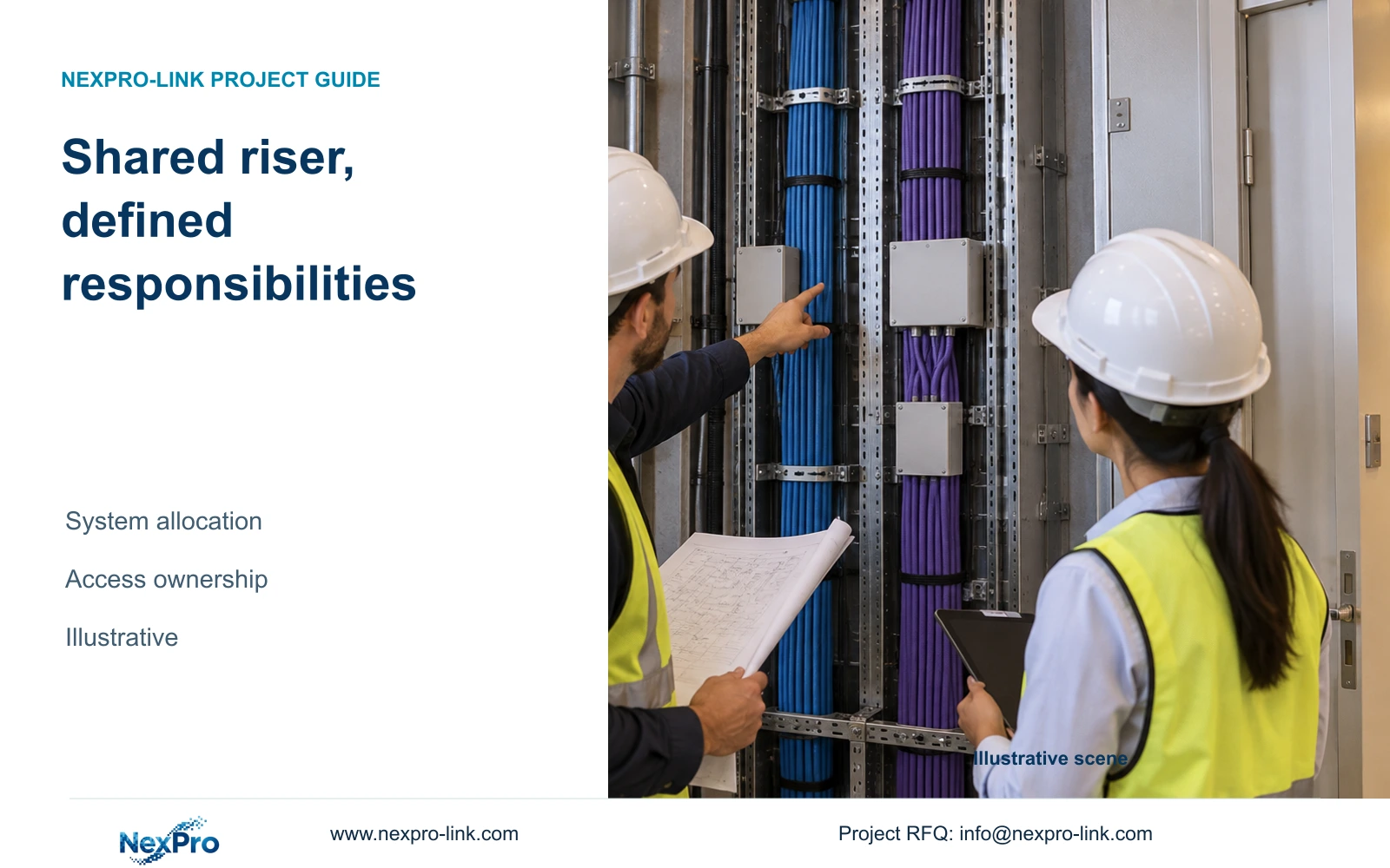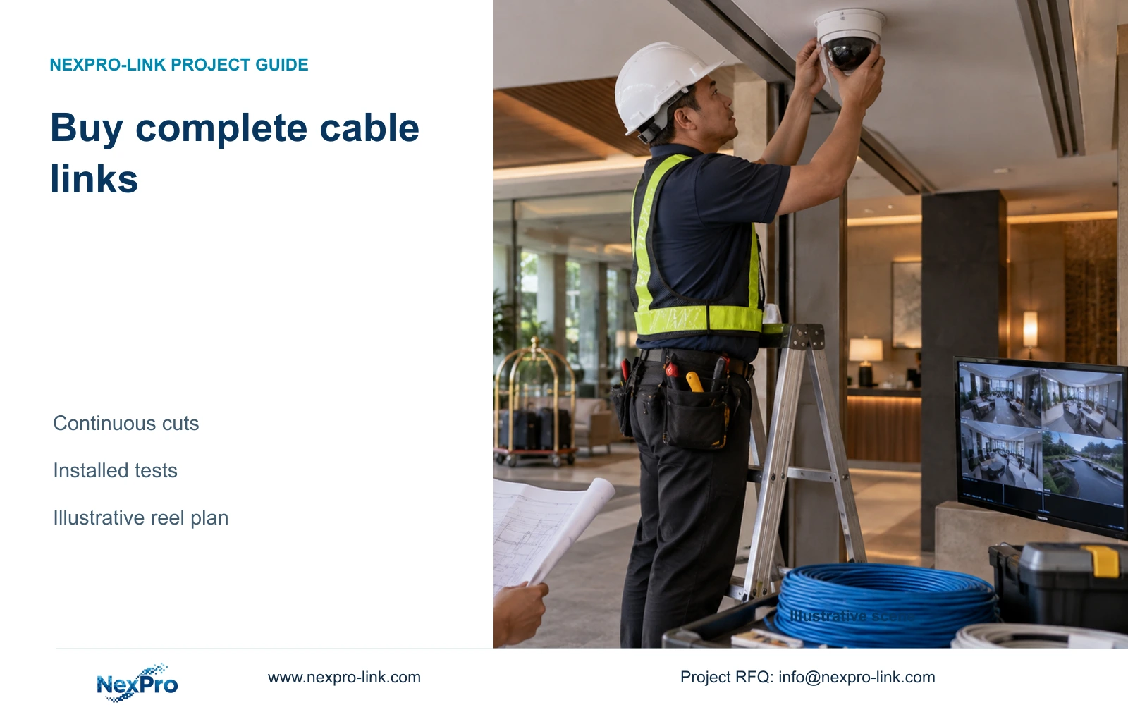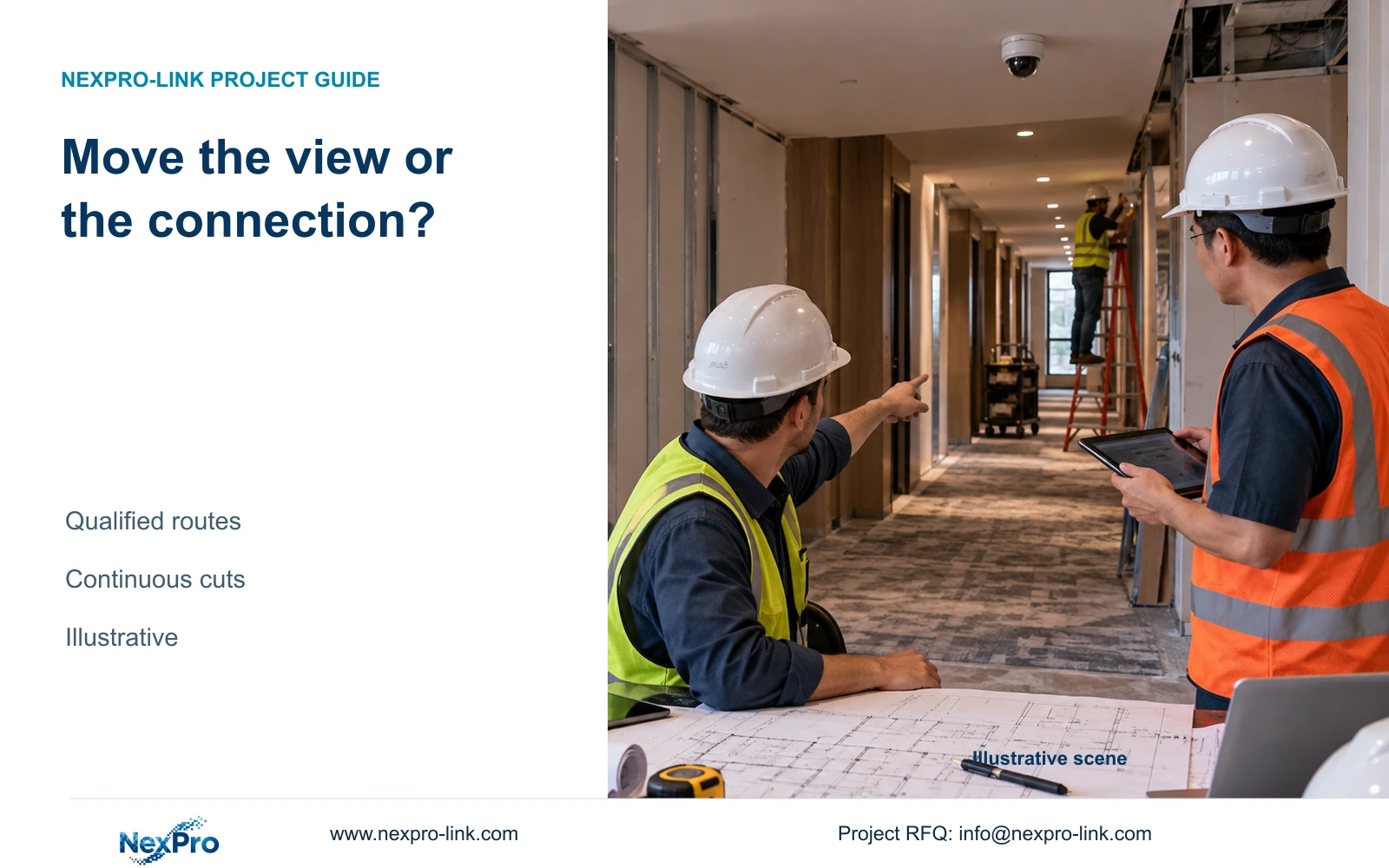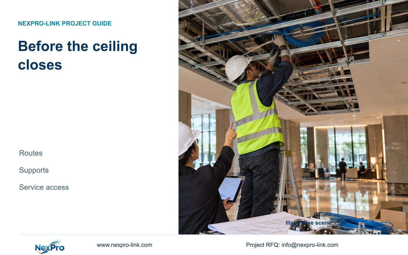
Camera purchase can remain pending while concealed routes and support interfaces are coordinated. Resolve link length, access and remote power before ceiling closure.
Section 01
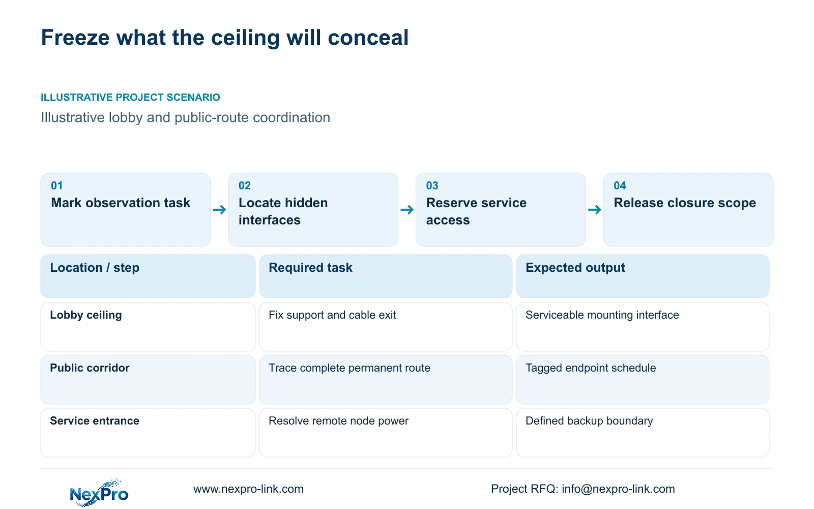
Identify concealed work that needs an early decision
Freeze cable routes, mounting support, maintenance access and network interfaces before closing the hotel ceiling when those elements would be difficult to alter afterwards. Final framing can remain adjustable within the approved installation arrangement. An unselected camera model is a reason to define interface limits, not to omit concealed-work coordination.
Mark the work that will disappear behind finished surfaces. Include the route to the camera, its cable exit, the support arrangement and access needed for termination or replacement. Separate those physical decisions from later image adjustments. A motorized lens can help refine framing within its supported range, but cannot resolve an inaccessible connection or an unsuitable mounting position.
Use public-zone observation tasks to establish the permitted position. A lobby overview and a corridor endpoint can need different locations even with the same camera family. The model need not be ordered to identify these tasks. If a position risks capturing an unnecessary private view, resolve the location and view boundary before its concealed support is installed.
| Required task | Given information | Decision still needed |
|---|---|---|
| Lobby overview | Ceiling closure approaching | Support, cable exit and service access |
| Public corridor endpoint | Observation task identified | Permitted position and complete route |
| Remote service entrance | Long route to core closet | Copper route or powered remote node |
Section 02
Locate cable and mounting interfaces
Give each proposed camera position a tag and connect it to a named termination point. Show the mounting surface and the space needed for the selected attachment, connector and servicing method. Where a model remains pending, record which dimensions or connection arrangements still need confirmation. Do not mark the entire location fully resolved while those fields remain open.
Keep the permanent cable route separate from patch cords. The Fluke source used here describes the typical 90 m permanent-link and 100 m channel bases. These are different boundaries. Cable category, sheath requirements, connection arrangement and the specified test basis must accompany the length review; a suitable length alone does not prove installed-link performance.
For procurement, distinguish bulk cable from termination components. SP5648 is a Cat6 48-port patch panel, and DT968MX is a Cat6 module. Neither identifies a box of cable or certifies the completed route. Specify the cable separately, then match patch panels, modules and cords to the actual closet layout and endpoint count.
| Item | Direct copper | Remote fiber node | Effect on installation |
|---|---|---|---|
| Data termination | Core closet to camera | Backbone to node, copper to camera | Different endpoint and port records |
| Power | PoE from core if fully connected | Local source for remote node | Additional electrical interface |
| Maintenance | Camera and core access | Camera, node and core access | Additional service location |
Section 03
Compare maintainable route options
Compare the complete direct route with relocating the closet or introducing a remote active node. Include enclosure space, equipment access and the source that powers each node. A fiber backbone transports data; it does not automatically supply power to the remote switch or its cameras. The remote source must also support the required outage behaviour.
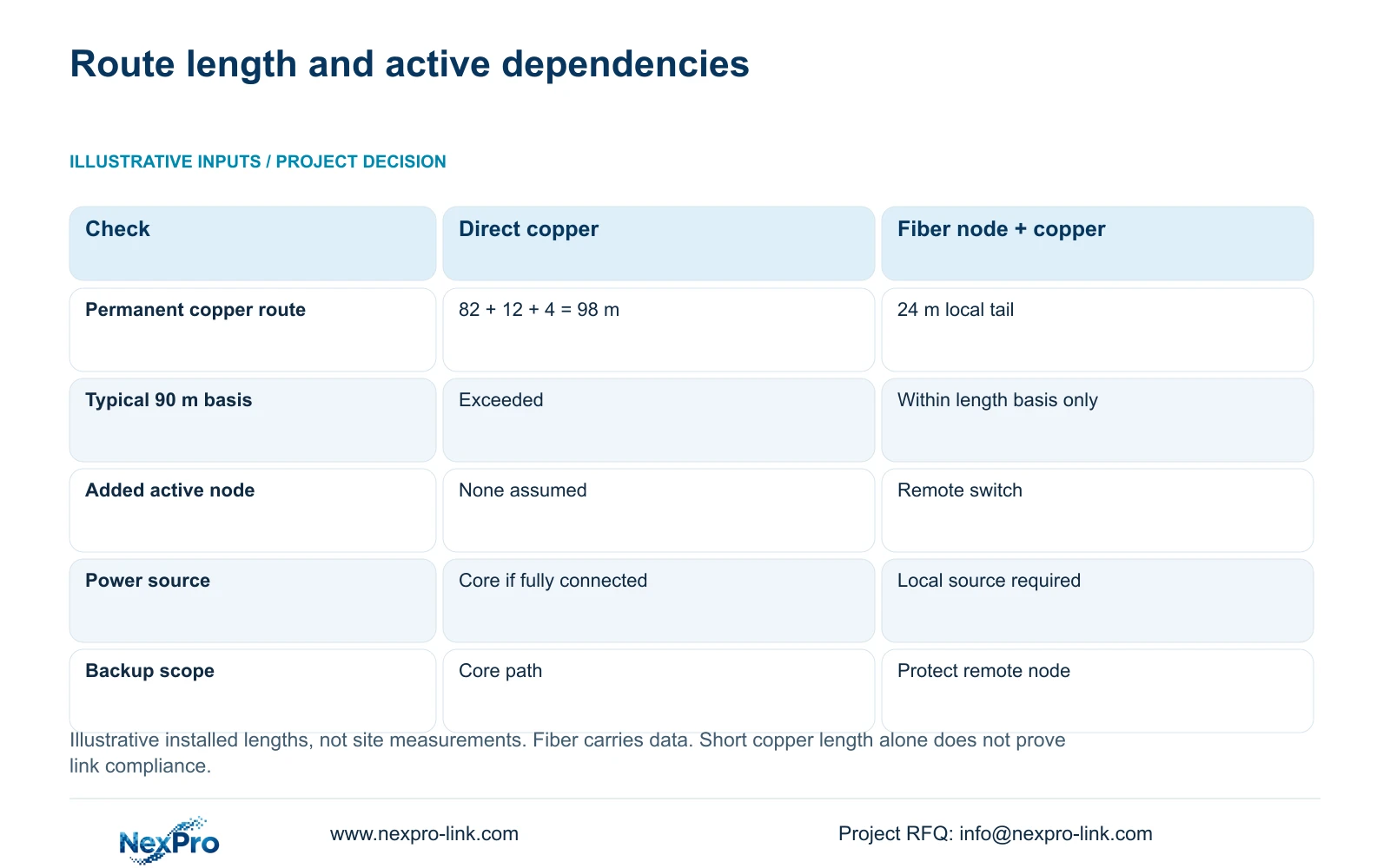
The illustrative route consists of 82 m horizontally, 12 m vertically and 4 m of termination allowance. Permanent route length is the sum of those components: 98 m. The alternative uses a qualified fiber node with a 24 m local copper tail. These are planning inputs, not site measurements or the cable quantities in CASE06.
An extender or additional switch changes the number of active dependencies, supported throughput and restoration responsibilities. Compare those consequences with the work needed to shorten the original route. Keep an accessible direct copper arrangement when it meets the selected link basis; introduce the remote arrangement only when its complete power and maintenance scope can be supported.
Section 04
Check link lengths and closet position
The 98 m permanent route exceeds the typical 90 m permanent-link basis used in this example. The 100 m channel figure does not provide extra permanent-cable allowance. Review the actual routing before ceiling closure, including vertical travel and termination provisions, so a straight-line plan dimension does not conceal the excess.
The 24 m local copper tail removes this particular length problem, but adds a remote switch and local power dependency. Its shorter length establishes only that it lies within the stated length basis. The fiber backbone, interfaces, port capacities and installed-link tests still need their own specification.
Evaluate moving the closet before accepting another active node. A revised location can shorten several routes, while also changing electrical supply, access and maintenance arrangements. If a remote PoE switch is proposed, NexPro SW-POE1618G remains an inquiry candidate: its source has conflicting access-port speed descriptions and no numerical total PoE budget. Confirm those fields before relying on it for the route.
| Metric / condition | Direct copper route | Qualified fiber node + local copper |
|---|---|---|
| Planned copper permanent route (m) | 98 | 24 |
| Typical 90 m permanent-link basis | Exceeds this basis | Within length basis only |
| Extra active dependency | None assumed | Remote switch and local power |
| Backup boundary | Core supply if fully connected | Remote node must also be protected |
Section 05
Coordinate access with other trades
Review camera servicing against the coordinated ceiling arrangement. Nearby building services can affect the approach to a connector or bracket even when the camera remains visible. The relevant question is whether the installation team can terminate, adjust and replace the equipment using the planned access after the finishes are complete.
Assign responsibilities for supports, ceiling openings and the local electrical source. The CCTV equipment schedule should identify the required interfaces, while appropriate local professionals resolve structural, electrical and safety requirements. A generic topology is insufficient as an installation drawing, especially when it introduces remote powered equipment.
In the illustrative phased hotel, first-phase work should preserve the interfaces needed for later public areas without assuming that all later equipment is already available. Record which concealed routes are being released now and which active components belong to the later package. Cost comparisons should include access provisions and local power work, rather than pricing only the added switch.
| Retained outcome | Extra scope | Worth choosing when | Counter-condition |
|---|---|---|---|
| Serviceable direct camera link | Route or closet adjustment | A qualified direct route remains practical | Revised route still exceeds its basis |
| Serviceable remote camera link | Node enclosure, power and backup | Backbone and local maintenance are supportable | No suitable remote power or access |
Section 06
Release the concealed-work information
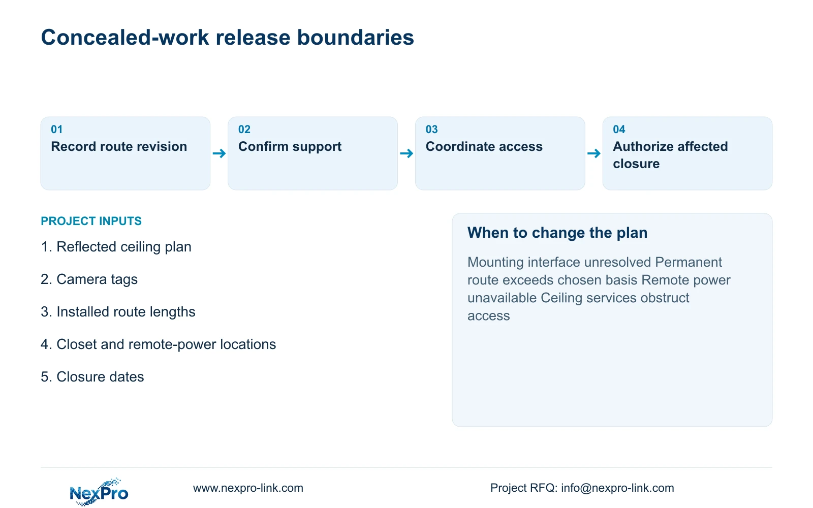
Issue a coordinated revision containing camera tags, routes, termination points, support interfaces and maintenance access. Identify unresolved model-specific details explicitly. Record the closure date and the person responsible for each remaining decision, so a pending camera purchase does not obscure whether the physical work can proceed.
Recommend freezing the low-reversibility work once the observation task and qualified route are established. Hold an affected location if mounting compatibility, safe support or service access remains unresolved. Reopen the route decision when a changed ceiling, closet location or remote-power arrangement invalidates the recorded basis; later framing adjustment cannot compensate for those changes.
For a focused proposal, send the reflected ceiling plan, camera tags, complete route lengths, closet locations and ceiling-closure dates to info@nexpro-link.com. Highlight any remote node without an agreed power source. NexPro-Link can discuss model matching and coordinated equipment through the hotel project and BOQ support routes; local installation responsibilities remain part of the written project scope.
Section 07
Buyer questions
Can we install concealed routes before buying the cameras? Yes, where the observation position, termination route and mounting interface limits are sufficiently defined. Keep unresolved model dimensions visible and avoid irreversible work that depends on an unconfirmed bracket or connector arrangement.
Can spare cable tails solve an overlength link? Short leftovers cannot justify an improvised splice or change the approved link basis. Plan continuous runs and the required termination arrangement. Reel procurement and installed-link length are separate checks.
What must accompany a remote fiber switch proposal? Include the backbone interfaces, local copper routes, enclosure and maintenance access, plus the local power and backup boundary. Confirm actual port speed and PoE output before treating the switch as suitable.
Engineering references
These sources support the general planning principles. Always use the selected product's current datasheet and applicable project standards for final design.