For each proposed network layer, identify the failed task it exposes and the team that restores it. Rehearse fault localization from camera node to recorder using the issued topology.
Section 01
Choose network layers from the site's service needs
For each proposed network layer, identify the failed task it exposes and the team that restores it. Rehearse fault localization from camera node to recorder using the issued topology. If an added layer creates an unowned service dependency without a required function, remove it from the proposal or assign its maintenance explicitly.
Use access, distribution and core layers only where scale, routing or maintenance requirements justify separate equipment. For a small factory, access switches connected to a suitable central aggregation point can be preferable when they meet the same capacity and service goals. Extra layers need an identified job and an accountable maintainer.
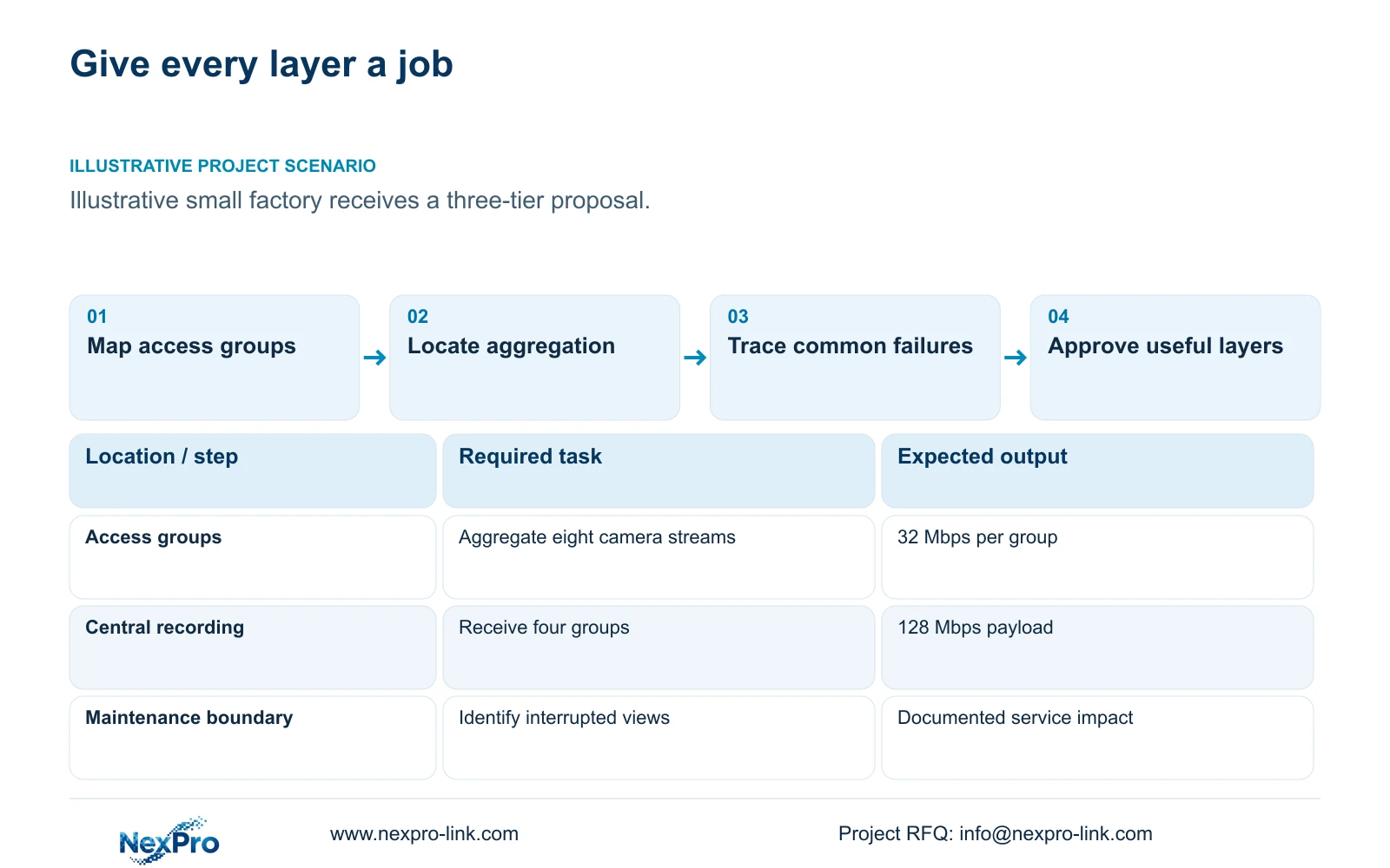
Illustrative project scenario: A small factory is offered a complex three-tier network similar to a large campus. Use CASE01 as the planning baseline: 32 ordinary security cameras, four eight-camera access groups and one central recorder. Consider a simple star first, then identify what a separate distribution layer would accomplish. No supplied site drawing establishes multiple buildings or redundant routes.
Mark camera groups, recorder location, cabinets, cable paths and electrical supplies on one working plan. Add the views affected by each switch, uplink and common device failure. This gives the owner a service decision to approve before the equipment list acquires layers based solely on terminology.
Section 02
Calculate the traffic that each layer would aggregate
With the reference assumption of 4 Mbps per camera, each eight-camera access group contributes 32 Mbps recording payload. The central recording path totals 32 × 4 = 128 Mbps. Determine where those groups converge and which physical interfaces carry the combined traffic before specifying uplinks.
A separate distribution switch becomes useful when it performs an actual building-level aggregation or approved routing task, or provides a defined maintenance boundary. If all four groups already reach one central location and the proposed distribution device merely forwards the same traffic to another adjacent switch, ask what operational requirement demands that additional stage.
Do not treat a new layer as additional usable bandwidth by itself. Check port availability, relevant overhead, concurrent services and the downstream recorder. The NVR4449 source lists 320 Mbps input and dual Gigabit LAN, but those fields do not establish the capacity of every switch or an automatic method of combining recorder interfaces.
Section 03
Define what remains available during maintenance
Write a maintenance scenario for the simple star. Replacing an access switch affects its assigned cameras; maintaining the common aggregation device can interrupt every group that depends on it. Additional distribution equipment may localise some work, but it can also introduce another shared component. Trace both arrangements rather than labelling the larger diagram resilient.
Record power dependencies beside data dependencies. CASE01 places its four switch groups within one electrical node. Moving access equipment into separate buildings changes power distribution and backup requirements; the original central UPS arithmetic cannot establish protection for remote mains-fed cabinets.
Factory IT owns the approved routing and management boundary, the security team defines tolerable loss of views, and the installer owns the physical schedule within its scope. NIST SP 800-82 Rev.3 supplies OT-security context for these boundaries. A manageable design should include configuration records, cabinet access and a recovery procedure the appointed team can actually use.
Section 04
Keep operator traffic distinct when comparing topologies
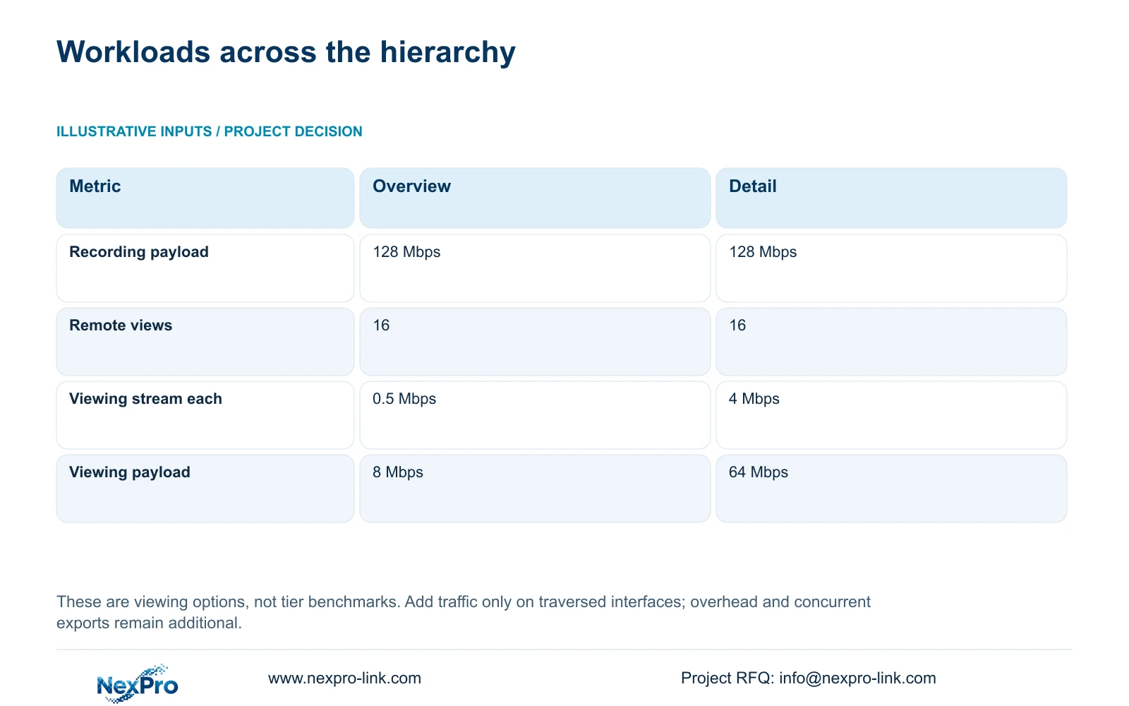
The supplied viewing calculation does not compare network tiers directly. It compares two operator workloads that either topology must carry where applicable. Recording remains recorder_Mbps = 32 × 4 = 128 Mbps. For 16 remote views, viewing_Mbps = 16 × stream_Mbps gives 8 Mbps at 0.5 Mbps each or 64 Mbps at 4 Mbps each.
The decisive difference is the client-facing payload, not the number of network layers. If local recording remains inside the security network, only the approved viewing traffic may cross a remote boundary. If the recorder is elsewhere, main-stream traffic may also traverse that boundary. Put the actual path alongside the calculation.
Approve an overview workflow where its detail is sufficient and supported. Include playback, export and shared-link traffic in the relevant simultaneous-use case. Neither the 8 Mbps figure nor an added distribution layer guarantees WAN performance, and substream support must be checked for the selected devices and client.
| Metric | Overview workflow | Detail workflow |
|---|---|---|
| Recording input | 128 Mbps | 128 Mbps |
| Simultaneous remote views | 16 | 16 |
| Viewing stream each | 0.5 Mbps | 4 Mbps |
| Viewing payload | 8 Mbps | 64 Mbps |
| Recording quality changed | No | No |
Section 05
Require a specific reason for each added layer
Prefer the simple star for the stated four-group baseline if its approved interfaces, routing and maintenance arrangements meet the project. Add building-level distribution when real routes and service boundaries make it useful. Consider separate core functions when the project has defined shared services or routing requirements that the simpler arrangement cannot satisfy.
Ask the bidder to describe each proposed switch's role in one sentence and identify what fails when it is removed. The cost team should then compare optics, patching, cabinet space, protected power and configuration work associated with that role. Do not invent savings from removing equipment without matching current quotations.
Preserve mandatory enterprise integration, owner network standards and specialist environmental requirements. A NexPro-Link alternative should explain deviations against the same accepted service, rather than offer fewer layers while omitting required management or support. Lower complexity is valuable only when the remaining design performs the agreed tasks.
Section 06
Release a topology that procurement and maintenance can share
The procurement package should contain a topology with named interfaces, an access-group schedule and a permitted traffic matrix. Distinguish supplied switches, retained infrastructure and optional future building connections. Identify the party responsible for routing, access rules, cabinet power and optical terminations so no shared dependency is left unpriced.
NexPro-Link's BOQ and Tender Support scope can coordinate recorder and related equipment matching against that design. The NVR4449 is a relevant central recording reference, but its published capacity does not select the site hierarchy. Project preparation and group labels should follow the approved drawing revision rather than a generic kit layout.
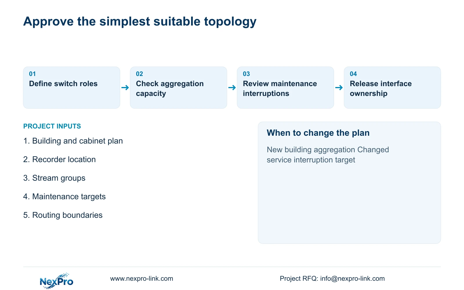
Before acceptance, demonstrate the agreed simultaneous workload and authorised access paths, then review a planned maintenance interruption under approved site conditions. Record observed impacts and recovery actions. Reassess the hierarchy when a new building, changed recorder location or tighter service requirement alters the original aggregation and maintenance assumptions.
Section 07
Buyer questions
Does a three-tier network automatically provide redundancy? No. Trace alternative paths, common equipment and power dependencies separately. Redundancy requires supported configuration and an accepted recovery test, not a layer count.
Can access and aggregation functions share one location? Yes, where the approved design meets port, traffic, routing and maintenance requirements. Separate functional roles do not always require separate physical switching layers.
What should trigger a hierarchy review during expansion? A new building route, additional shared services, changed recording location or revised maintenance target can justify reassessment. Confirm the changed dependency before adding a layer.
Section 08
Compare a simple star with justified expansion
Send your building and cabinet plan, recorder location and stream groups, maintenance interruption requirements, and IT/OT routing boundaries to info@nexpro-link.com for a scope-matched topology discussion.
Engineering references
These sources support the general planning principles. Always use the selected product's current datasheet and applicable project standards for final design.