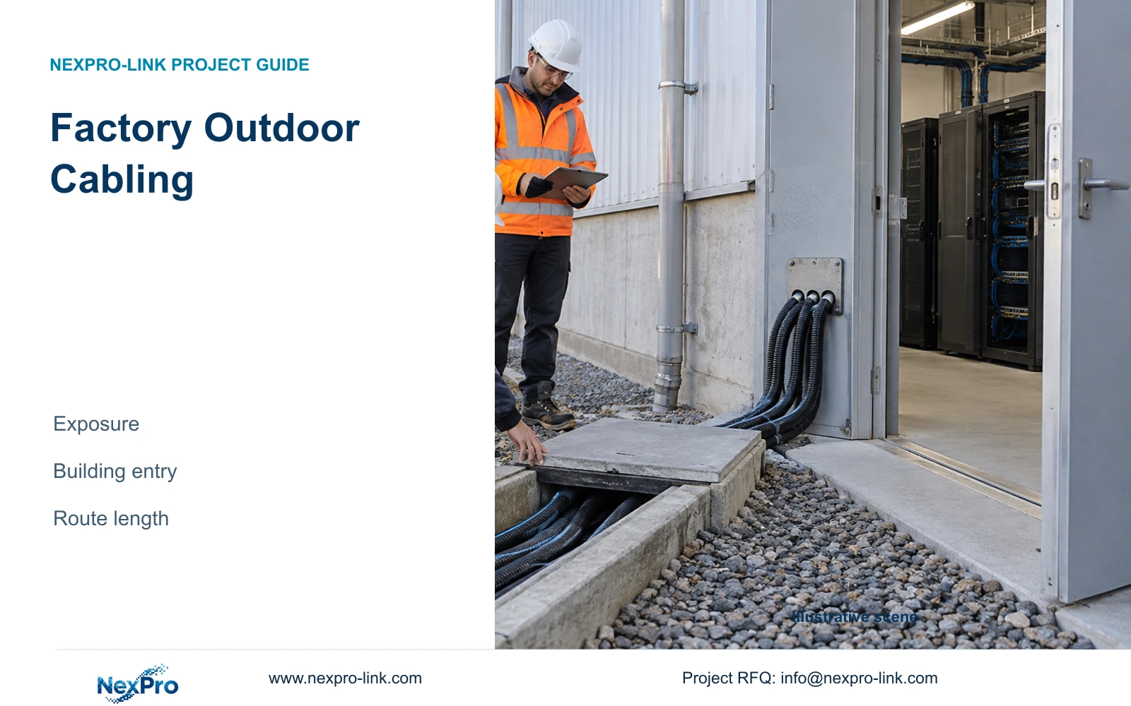
At each building entry, map the exposed segment, proposed transition and indoor continuation to their exact product evidence and local approval owner. Recalculate the continuous lengths after the accepted transition moves.
Section 01
Specify cable construction for each exposure segment
At each building entry, map the exposed segment, proposed transition and indoor continuation to their exact product evidence and local approval owner. Recalculate the continuous lengths after the accepted transition moves. Hold an undocumented segment separately; an outdoor suitability claim cannot silently approve the indoor continuation or an inaccessible termination.
Factory outdoor cabling should be specified against actual exposure and the building-entry arrangement. An indoor CAT6 category description does not establish suitability for sunlight, wet ducts, burial or the indoor portion of an entering cable. Map the complete route and request product evidence for every condition before accepting a cable substitution.
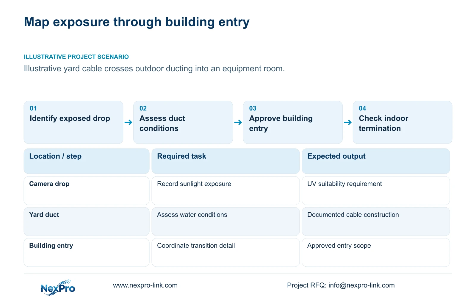
Illustrative project scenario: A yard route passes through outdoor ducting before entering an indoor equipment room. Assume the camera-end drop has an exposed section and the project team has not confirmed whether the duct remains dry. The engineer needs a cable schedule that covers those uncertainties and identifies the point where outdoor routing meets the building installation.
Divide the route into exposed drop, duct, entry and indoor travel. Record expected water exposure, mechanical conditions and operating environment without treating an enclosure label as evidence for the cable inside it. Ask the local design team to confirm relevant installation and building requirements. Keep unknown exposure conditions visible instead of allowing the supplier to assume a sheltered indoor route.
Section 02
Coordinate the entry before deciding on one continuous product
Mark the entry location, cable support, sealing arrangement and any planned transition on the drawing. Confirm who provides the penetration and reinstatement work, and leave sufficient access to inspect and maintain the connection. These details affect both installation scope and the cable length that the estimator must include.
One continuous cable may be a candidate if its documented construction and the approved installation arrangement suit every route segment. If a transition is required, design its accessible location and connection method explicitly. Do not splice arbitrary remnants simply to bridge outdoor and indoor stock, and do not insert an unreviewed joint into the link after the purchasing schedule has been approved.
The local project team should verify the applicable building-entry and fire-performance requirements. No universal permitted indoor distance, fire classification or sealing detail is established by the supplied material. The tender should request the relevant evidence and define the approval responsibility rather than copy an assumed requirement from another country or project.
Section 03
Choose copper and fibre according to their network roles
Use copper as a candidate for suitable local camera links where the approved route, application and PoE arrangement fit. Treat a fibre backbone as a separate system with its own cable construction, optical interfaces and termination locations. A fibre-fed yard node may shorten local camera runs, but it adds an equipment and power location that must be maintained.
Draw the data path and power path separately. Cameras can receive power from the selected local PoE switch; the fibre connection does not provide that switch's AC backup. Identify local mains, protected outlets and the suitable cabinet environment before presenting the node as an accepted alternative. Include the relevant enclosure and service access in the quotation.
CASE01's 32-camera baseline has 1,872 m of continuous copper cuts and a feasible seven-reel allocation. Cross-building fibre, outdoor cable construction, ducting and entry work are separately defined scope. Its total cannot be used to purchase all yard cable under one generic indoor specification, and a new local node would require revised copper routes and quantities.
Section 04
Include entry detours in the individual length check
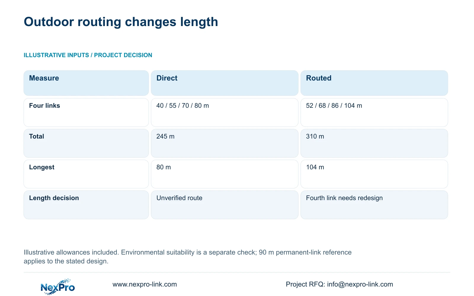
The supplied four-link illustration starts with direct distances of 40, 55, 70 and 80 m. Routes through trays and vertical rises, including installation allowances, become 52, 68, 86 and 104 m. With total_m = sum(individual_link_lengths), the estimate changes from 245 m to 310 m. These are illustrative route inputs, not surveyed yard measurements.
Fluke Networks guidance distinguishes a typical 90 m permanent link from a 100 m complete channel. The planned 104 m permanent link needs a revised route or architecture. Outdoor-suitable construction does not resolve that length issue. Check whether an approved nearer entry, cabinet relocation or fibre-fed node preserves the camera view while giving the network a suitable link boundary.
The comparison shows why environmental and length acceptance must be independent. Even the shorter routed links need the correct exposure specification. Conversely, a cable with the required exposure evidence still needs a suitable continuous route and termination design. Final reel allocation should follow the accepted correction, with different cable constructions kept in separate stock groups.
| Measure | Direct-distance basis | Routed installation basis |
|---|---|---|
| Four links | 40 / 55 / 70 / 80 m | 52 / 68 / 86 / 104 m |
| Total cable | 245 m | 310 m |
| Longest planned permanent link | 80 m | 104 m |
| Length decision | Installed route unverified | Redesign fourth link |
| Exposure acceptance | Not established | Still requires cable evidence |
Section 05
Compare complete yard-route alternatives
Prefer a continuous, documented cable arrangement for suitable local copper routes, with the entry details approved before ordering. Change to a transition or fibre-fed arrangement when the full route cannot be served by the proposed product or when the accepted length and maintenance assessment justify another architecture. Keep the observation task unchanged in each option.
Compare outdoor copper and a fibre-fed local node using cable construction, supports, duct access, entry works, optical equipment and local power scope. Include installed testing and future service access. A quotation that includes only metres of cable cannot demonstrate which option is cheaper to complete, and there is no supplied market-price evidence for a cost winner.
A changed route can alter installation timing as well as quantities. If the entry cannot be completed before equipment-room finishes, record the enabling work and release date rather than assuming the cabling crew can improvise another penetration. Keep unaffected camera packages available for release, while holding the unresolved yard link and its cable cuts until the coordinated detail is accepted.
Section 06
Procure environmental evidence with the termination schedule
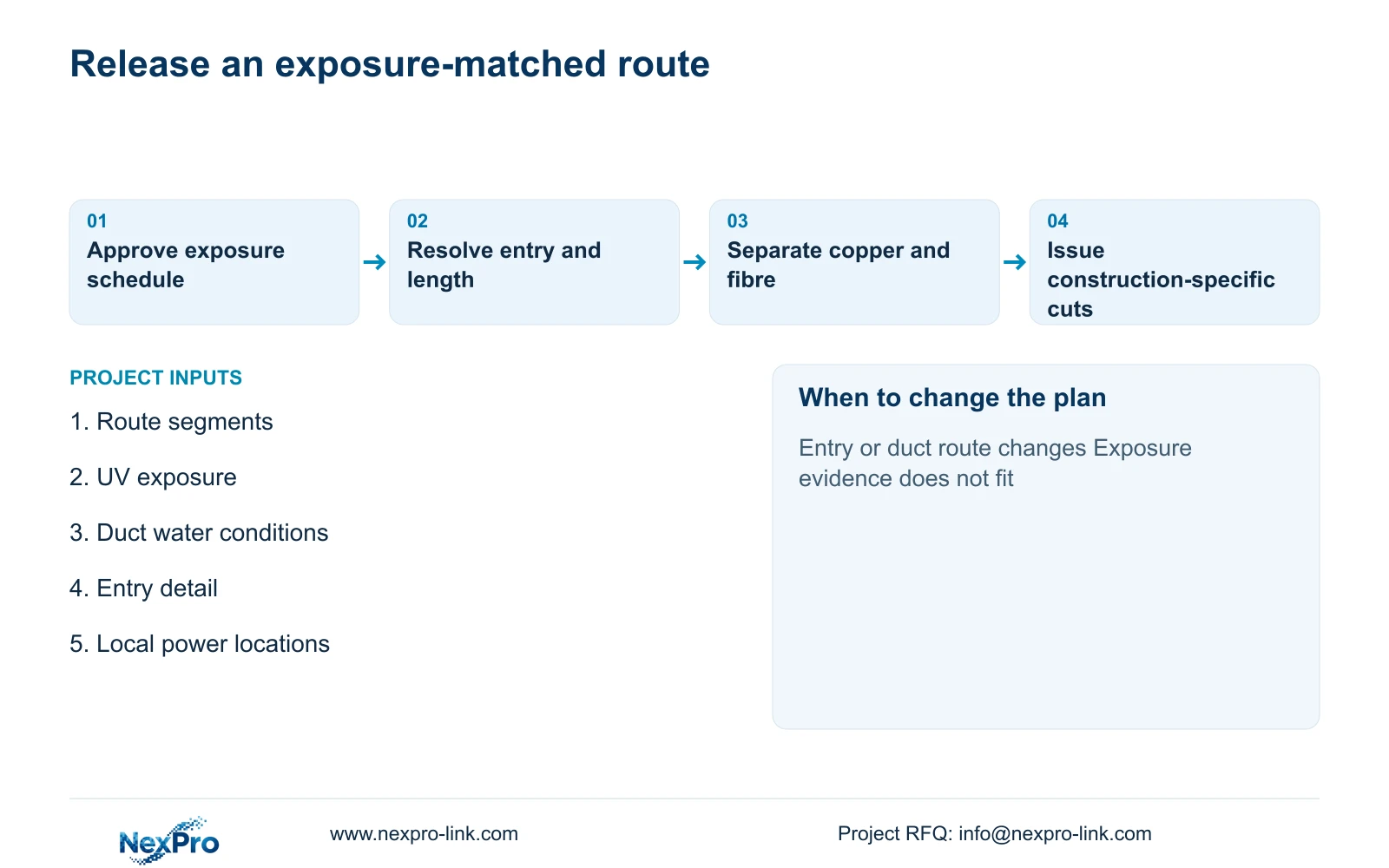
Issue a route-segment schedule listing cable type, continuous length, exposure conditions and accepted entry arrangement. Attach the exact proposed cable data and identify any missing UV, water, mechanical or indoor-use evidence. Require alternative products to address the same conditions rather than offering a category label as a complete technical response.
NexPro-Link's Structured Cabling references include SP5648, a Cat6 48-port patch panel, and DT968MX, a Cat6 tool-less module. These can be discussed for suitable termination locations. They are not bulk outdoor cable models and do not establish an exposed connector assembly's suitability. Keep panels and associated infrastructure in the approved service environment.
NexPro-Link's BOQ support can help coordinate the relevant equipment and documented deviations, while local contractors retain entry, containment and installation responsibilities. At handover, reconcile cable IDs, entry locations and test records with the as-built drawing. Preserve the accepted route and exposure specification so future replacement work does not substitute indoor stock simply because the connector fits.
Section 07
Buyer questions
Can outdoor ducting justify using an indoor cable? Only if the actual conditions and the product's documented suitability support the approved arrangement. Do not assume a duct removes water or every other environmental exposure.
Must all yard routes use fibre? No. Suitable local copper links remain candidates. Compare fibre when route length, site conditions or the backbone task justify it, and include local switching and power.
What should happen if the final entry moves? Update the exposure segments, continuous lengths, termination detail and affected stock allocation. Recheck the link boundary before approving the changed installation.
Section 08
Specify the yard route for quotation
Send your outdoor route drawing, UV and water exposure conditions, proposed building-entry detail and local cabinet power plan to info@nexpro-link.com to discuss the cable and equipment supply boundaries.
Engineering references
These sources support the general planning principles. Always use the selected product's current datasheet and applicable project standards for final design.