Plan joint acceptance with the lift contractor: first verify fixed-landing handovers, then the approved cabin transmission and power arrangement during representative travel. Record which party witnesses each interface.
Section 01
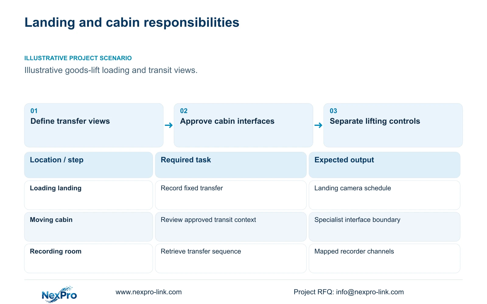
Separate landing evidence from moving-cabin observation
Plan joint acceptance with the lift contractor: first verify fixed-landing handovers, then the approved cabin transmission and power arrangement during representative travel. Record which party witnesses each interface. If cabin approval is absent, accept only the independently completed landing scope and preserve the missing transit interval as an exclusion.
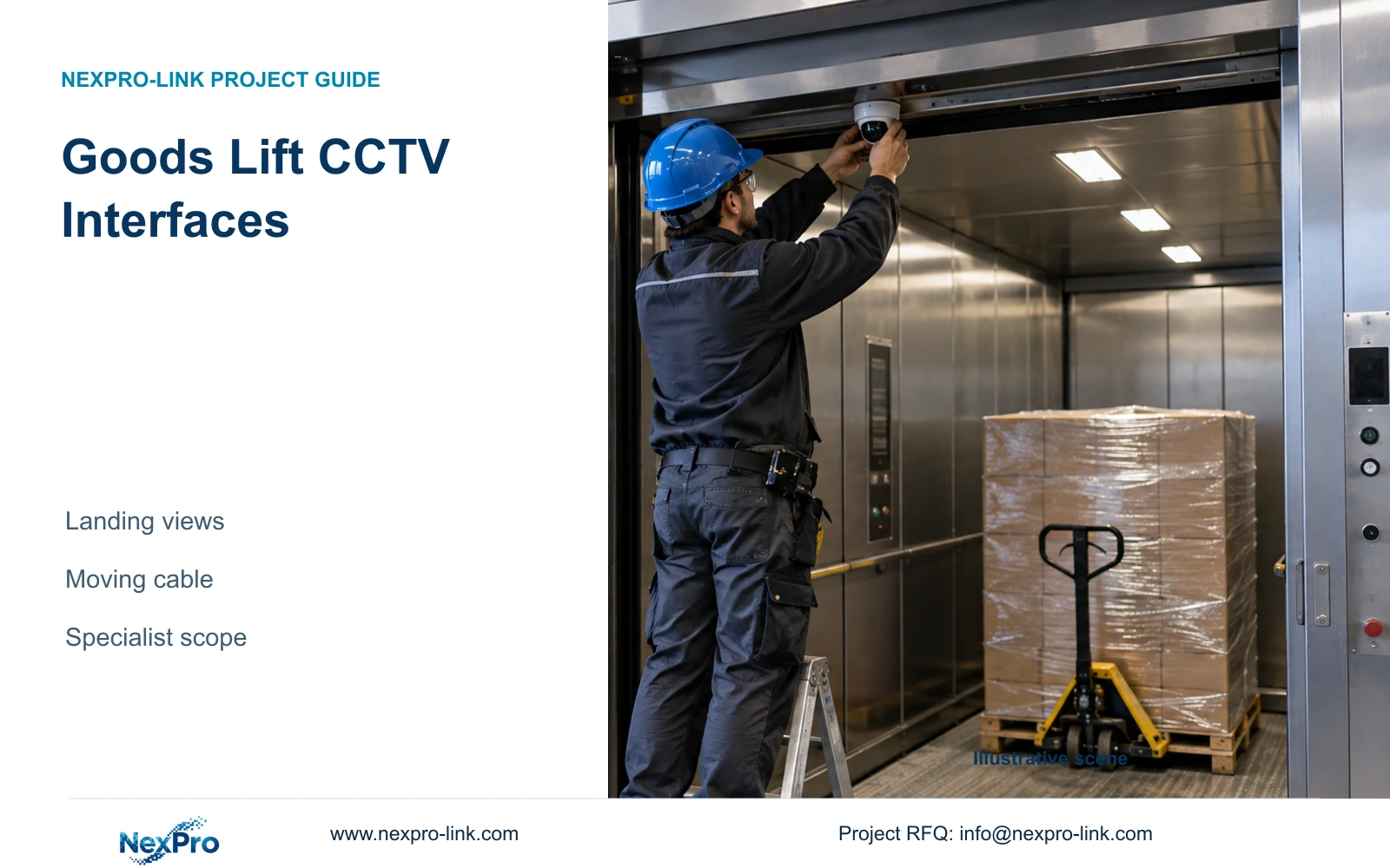
Factory goods lifts and loading platforms should have separate CCTV tasks for fixed loading positions and moving cabins. Fixed landing cameras can document approach and transfer context. Cabin equipment needs the lift contractor’s approved mounting, power and transmission method. Ordinary fixed CAT6 routing should not be specified as a substitute for a suitable travelling-cable design.
Illustrative project scenario: A goods lift needs video at loading landings and potentially inside the moving cabin. Assume the owner wants to review pallet handovers at fixed landing positions and is considering a cabin view for the interval between them. The cabin view remains conditional until its operational purpose and specialist interfaces are agreed.
Draw the transfer sequence before selecting equipment. Identify the goods approach, landing threshold and cabin interior as separate observation areas. Check where pallets or operators block the exchange. A cabin image may provide transit context while failing to show the external handover; a landing camera cannot be assumed to show the whole cabin during travel.
Section 02
Obtain the specialist transmission boundary before selecting cabin hardware
Ask the lift contractor to define the permitted camera mounting location, cabin power interface, transmission method and termination points. Include the route and access arrangements for maintenance. The CCTV supplier can then evaluate the camera and recording interface against that information. Camera PoE support does not establish that the proposed moving connection can carry both power and data.
Keep the fixed building link and moving section as different BOQ items. The former has surveyed routes, endpoints and a stated test method. The latter follows the specialist’s approved system scope and installation responsibility. Any required adapters or transmission equipment must be identified explicitly; an unspecified allowance should not imply that those devices are included.
If cabin observation is optional, release the fixed landing package first only when it can operate independently and the owner accepts the missing transit view. If cabin footage is necessary for the approved task, retain the whole cabin scope as a coordinated dependency. Do not ship a camera with an unresolved connection and expect the installer to improvise the final method.
Section 03
Leave lifting controls outside the CCTV operating path
Specify observation and recording without assigning movement permission, overload control or lifting safety functions to CCTV. The lift or platform specialist retains the control design and verifies applicable local requirements. If an approved status signal is requested for video context, document its source, destination and purpose separately from any command path.
Use the interface schedule to allocate supplied cameras and recording equipment, specialist-provided cabin mounts and transmission, retained lift controls, and installer-provided fixed cabling. The owner approves the review task; the lift contractor approves work affecting its equipment. Equipment coordination does not itself establish software integration or life-safety control.
Power boundaries need the same care. A CCTV UPS may protect the local recording and network node, but it does not thereby back the lift motor or certify continued lifting operation. Cabin-camera continuity depends on its approved power path. Any requested outage observation should identify which cameras, link devices and recorder must remain operational.
Section 04
Check every fixed link before converting metres into reels
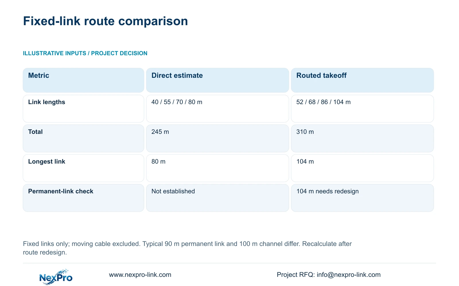
The illustrative fixed-link takeoff compares direct distances of 40, 55, 70 and 80 m with routed lengths of 52, 68, 86 and 104 m, including the supplied installation allowances. Total_m = sum of individual link lengths. The direct total is 245 m; the routed total is 310 m. These figures describe fixed links only, not cabin travelling cable.
The 104 m planned permanent link is the decisive issue. Fluke guidance distinguishes a typical 90 m copper permanent link from a 100 m complete channel. The direct drawing distance did not establish compliance, and the routed result identifies a link needing redesign. Relocate the cabinet or evaluate an appropriate alternative path before freezing quantities and equipment.
Keep individual lengths in the takeoff after the total is calculated. Dividing total metres by reel length cannot confirm that every continuous cut fits or that every installed link meets its design. A redesigned route changes endpoints, local power or fibre equipment and therefore needs a revised material list. Do not solve the 104 m issue by hiding it inside a general cable allowance.
| Metric | Direct-distance estimate | Routed design takeoff |
|---|---|---|
| Individual links | 40 / 55 / 70 / 80 m | 52 / 68 / 86 / 104 m |
| Total cable | 245 m | 310 m |
| Longest link | 80 m | 104 m |
| Typical permanent-link check | Not established | One link needs redesign |
| Procurement consequence | Provisional budget only | Resolve route before order |
Section 05
Recommend fixed landing supply with a defined cabin option
Use independently functioning landing views as the baseline where they satisfy the owner’s evidence task. Add cabin observation when a documented gap remains and the lift contractor approves the complete interface. Compare quotations with the same task, specialist installation and maintenance access. A package omitting moving transmission is not equivalent to one that includes it.
For suitable ordinary fixed locations, the NexPro-BL2812M55-5MP-DIC-AI offers listed 2880×1620 output and a 2.8–12mm motorized lens. Its IP66 field does not establish suitability for every cabin, vibration condition or cleaning regime. Match the mounting environment and actual view separately. NexPro-Link’s structured-cabling references identify SP5648 patch panels and DT968MX modules, not a travelling-cable or bulk-cable SKU.
CASE08 uses four local 32-camera nodes and fixed camera links of 41 to 76 m. That illustrates a workable node-allocation method, not permission to reuse its lengths around a lift shaft. Assign landing and any approved cabin feed to the appropriate recorder, check supported streams and retention, and keep remote node power and authorized viewing responsibilities distinct.
Section 06
Schedule acceptance around fixed and moving interfaces
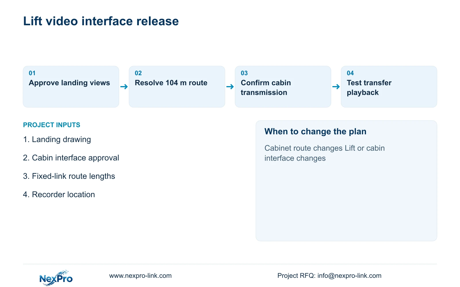
The project package should include landing camera tags, fixed cable endpoints, the cabinet location and the specialist cabin connection boundary. Identify mounting accessories, recorder assignment and the required handover sequence. List unavailable approvals as unresolved items rather than leaving a blank line that a buyer could mistake for an included service.
NexPro-Link can discuss ordinary-camera matching, recording equipment, structured-cabling components and coordinated BOQ documentation. Packing can distinguish fixed landing units from any separately approved cabin equipment. Local fixed-link installation and specialist lift work should keep their own responsible parties and acceptance records, even if commercial supply is coordinated.
Test landing playback during representative loading, then test any cabin view through the approved operating range under the specialist’s supervision. Confirm timestamp continuity and authorized retrieval across the transfer sequence. Revisit the design after a changed cabinet route, lift specification or loading pattern, since each can alter both observation and infrastructure scope.
Section 07
Buyer questions
Can the cabin camera be bought before the transmission method is final? It can be proposed as a conditional candidate, but final selection and release should match the approved mounting, power and transmission interface. Keep unresolved adapters and specialist work visible in the order scope.
Does the 310 m total determine the final reel quantity? No. It remains a preliminary routed total with one link needing redesign. Final procurement also needs continuous cut allocation, the revised route and separately approved spare material.
Can a CCTV display tell an operator that lifting is safe? The proposed CCTV role is visual context. Lifting authorization and safety decisions remain within the specialist control system and operating procedure.
Section 08
Coordinate the landing and cabin scope
Send the landing-view drawing, lift contractor’s approved cabin interface, routed fixed-link lengths and recorder location to info@nexpro-link.com for a coordinated CCTV supply proposal.
Engineering references
These sources support the general planning principles. Always use the selected product's current datasheet and applicable project standards for final design.