For every intermediate active device, record its power source, permitted service approach and replacement method. Compare a failed-device visit under normal factory access restrictions for each alternative.
Section 01
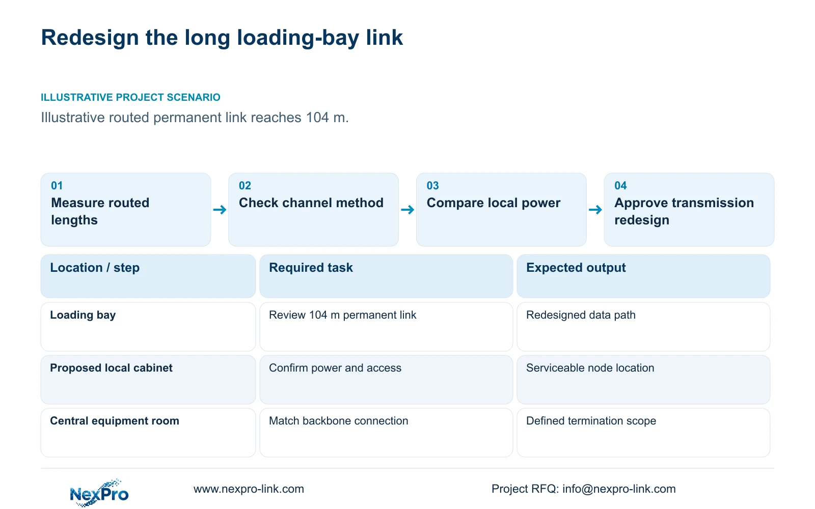
Measure the routed link before choosing transmission
For every intermediate active device, record its power source, permitted service approach and replacement method. Compare a failed-device visit under normal factory access restrictions for each alternative. Keep any inaccessible node as an unresolved dependency, even if the advertised link distance fits; transmission reach does not establish maintainability.
For factory camera links beyond ordinary copper channel distance, choose a supported transmission arrangement and suitable power at the remote end. First check whether relocating a cabinet can bring the complete link within the approved copper design. Otherwise compare fibre and a local node with a specifically qualified extender arrangement.
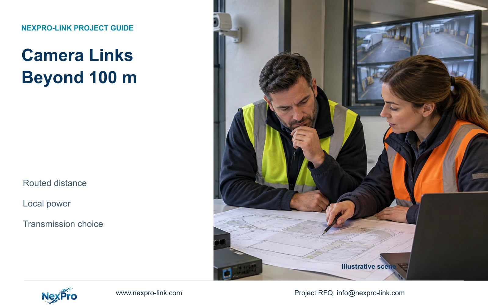
Illustrative project scenario: A remote loading bay is beyond ordinary copper Ethernet channel distance. A four-link worksheet initially uses straight-line distances of 40, 55, 70 and 80 m. Following trays, vertical rises and installation allowances changes those estimates to 52, 68, 86 and 104 m. The remote bay needs redesign before cable procurement.
Keep permanent-link and complete-channel measurements separate. The supplied Fluke Networks guidance distinguishes a typical 90 m permanent link from a 100 m complete channel. Patch cords and the selected termination method matter. Actual technology and installation requirements govern acceptance; a straight-line drawing measurement cannot establish compliance.
Section 02
Compare the data route and power route together
Cabinet relocation can preserve ordinary copper links if the revised location has suitable power, access and cable routes. Confirm all affected endpoints after the move. Shortening the loading-bay connection may lengthen another camera route, so assess the complete group rather than solving only the longest line.
Fibre with a local access node separates the backbone data route from camera power delivery. Specify compatible optics and terminations at both ends, then provide an appropriate local supply for the remote switch and cameras. Protect that local supply where the outage objective requires it; a UPS at the central recorder does not power the remote node through fibre.
An extender is a conditional option when its exact model supports the proposed distance, endpoint power, throughput and environment. Obtain the manufacturer's supported arrangement and locate each active device on the drawing. Do not assign an invented extender SKU or treat a generic long-distance claim as proof of usable power at the camera.
Section 03
Locate every added device where it can be maintained
Compare the service consequences before approving an active intermediate point. An extender above a busy loading lane needs an agreed access method, enclosure and replacement procedure. A local cabinet requires space, power and maintenance ownership. A fibre path requires accessible termination records and identified optical components.
Prepare a node schedule showing equipment role, location, power source and responsible party. Include the approved camera group and stream path. The installer confirms the route and accessible mounting arrangement; the supplier documents supported equipment limits; the owner decides acceptable maintenance interruption.
NexPro-Link's Structured Cabling scope includes the SP5648 Cat6 48-port patch panel and DT968MX tool-less module. These are termination references, not bulk cable or long-distance transmission devices. Their selection should follow the revised link method; they cannot make an overlength copper run acceptable by themselves.
Section 04
Use individual lengths to expose the redesign
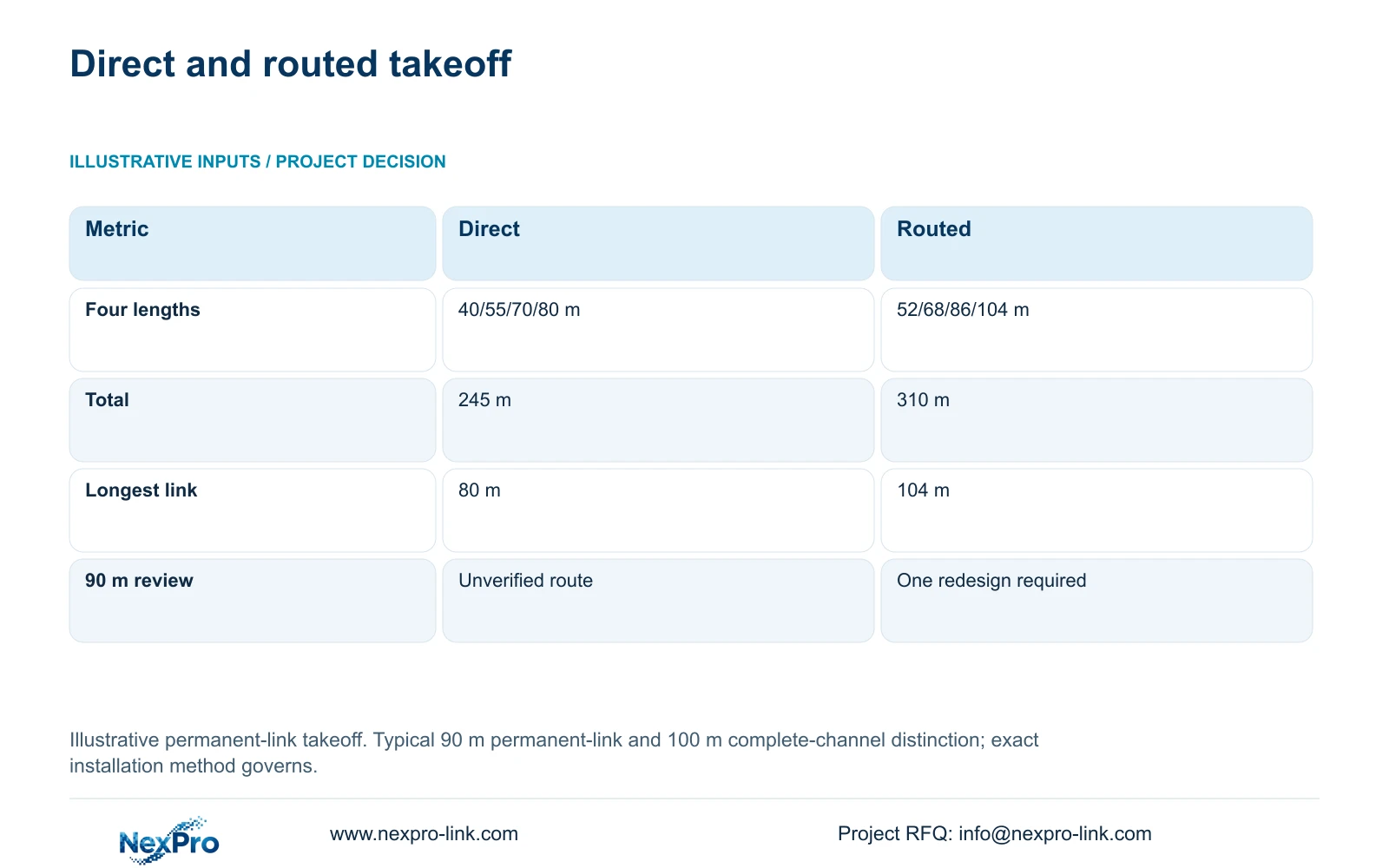
Calculate total_m = sum(individual_link_lengths). The direct estimates give 40 + 55 + 70 + 80 = 245 m. The routed takeoff gives 52 + 68 + 86 + 104 = 310 m. More importantly, the longest planned permanent link becomes 104 m and exceeds the typical 90 m design basis.
The decisive difference is an individual link problem hidden by the original takeoff. Buying more cable cannot resolve it. Redesign that path by relocating the cabinet or specifying a supported alternative, then calculate material quantities for the approved arrangement.
Keep this four-link module separate from CASE01, whose 32 assumed permanent links are 41 to 76 m and total 1,872 m. That reference's seven-reel feasible cutting plan does not validate this remote-bay route. Recalculate continuous cuts after redesign; total metres divided by reel length alone does not establish a workable cutting schedule.
| Check | Direct estimate | Routed takeoff |
|---|---|---|
| Individual lengths | 40 / 55 / 70 / 80 m | 52 / 68 / 86 / 104 m |
| Total cable | 245 m | 310 m |
| Longest permanent link | 80 m | 104 m |
| 90 m design review | Not established by direct distance | One link needs redesign |
Section 05
Prefer the option with a supported and serviceable dependency chain
For a remote loading area with suitable local power and an available backbone route, prefer evaluating fibre and a local node as the main alternative. For a modest route correction, cabinet relocation may be sufficient. Select an extender only when its exact supported arrangement and maintenance access meet the same task.
Keep the power review explicit. CASE01 uses assumed 12 W camera demand and an assumed switch AC calculation; these inputs do not establish the remote cabinet's actual load or runtime. Include optics and any intermediate devices in the relevant local power schedule, then obtain supported battery and equipment data.
Compare quotations for the same accepted loading-bay evidence, outage objective and service boundary. Include civil routes, terminations, cabinet supply, testing and local electrical work where required. NexPro-Link can coordinate equipment requirements, while the local team confirms construction and installation responsibilities. No supplied data establishes a universal lowest-cost option.
Section 06
Order against the revised route and acceptance method
The final BOQ should identify which original copper links remain, which route is redesigned and which transmission components are newly supplied. Include termination method, location IDs and the relevant test requirements. If a direct-plug or another channel arrangement replaces module-ended links, update the material count and acceptance method together.
NexPro-Link's BOQ and Tender Support scope can help translate the chosen route into model requirements and quotation deviations. Project packing should keep local-node equipment and accessories identifiable. Confirm retained cable condition through the appropriate site checks rather than assuming that an existing connection can support the revised design.
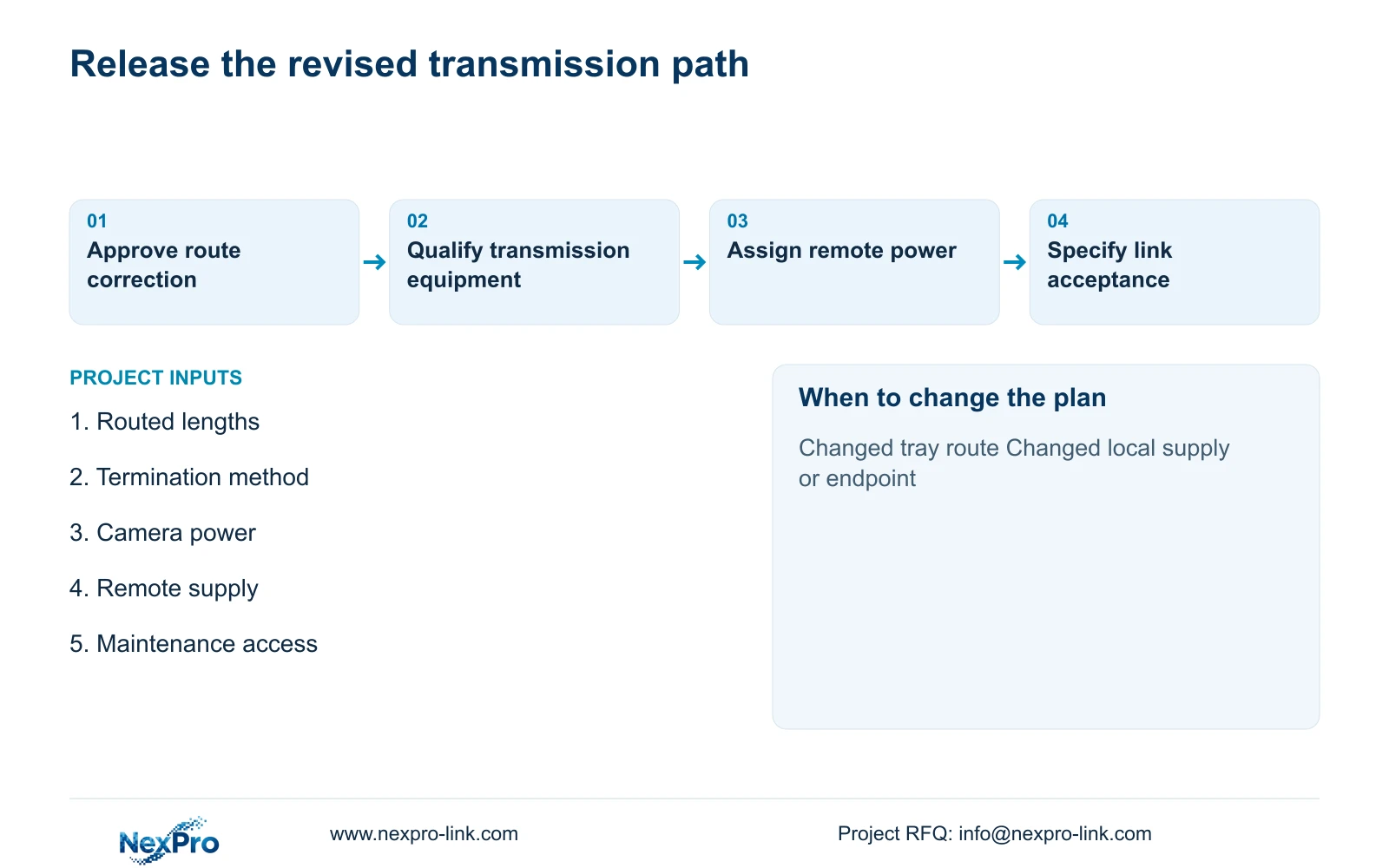
Before handover, verify the selected link under the required camera functions and recording workload, then inspect the recorded footage and maintenance records. Check remote power interruption separately from data interruption under an approved test plan. Reopen the design if the tray route, local supply or camera power changes before installation.
Section 07
Buyer questions
Does Cat6 automatically allow a longer camera run? No. Cable category alone does not establish an extended supported channel. Review the exact transmission method, route, terminations and acceptance requirements.
Can we keep the central UPS when installing fibre? It may continue protecting central equipment. A remote mains-fed switch needs its own approved power protection if it must remain available during a local outage.
Should an extender be rejected in every factory? No. It can be considered when its exact supported distance, power, throughput and installation conditions fit. Include intermediate access and replacement work in the comparison.
Section 08
Resolve the remote loading-bay link
Send the routed length and termination plan, camera group and maximum power data, available remote supply, and maintenance-access conditions to info@nexpro-link.com to compare a suitable transmission package.
Engineering references
These sources support the general planning principles. Always use the selected product's current datasheet and applicable project standards for final design.