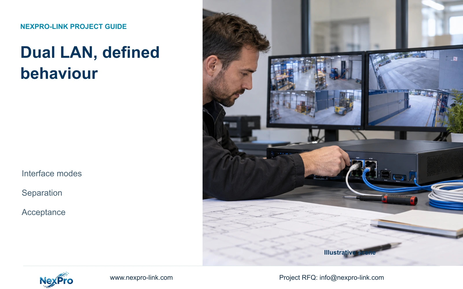
Two NVR network sockets establish a hardware feature, not a complete continuity design. Verify interface modes, approved traffic paths and recorded failure behaviour.
Section 01
Verify what each network interface can actually do
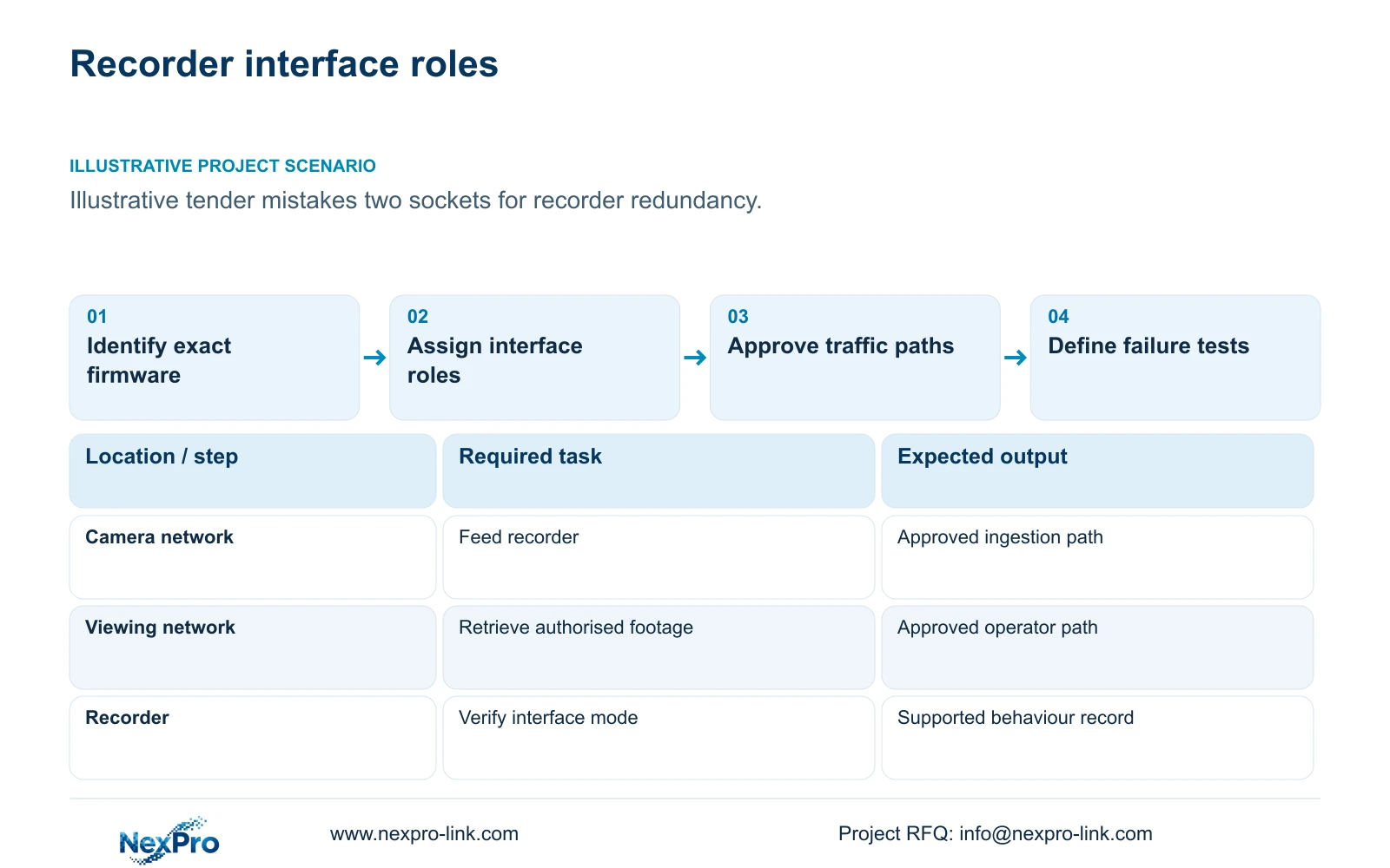
Dual LAN on a factory NVR should be specified by supported interface behaviour, not socket count. Network separation, bandwidth aggregation and link failover are different capabilities. Obtain documentation for the exact recorder and firmware, identify the approved mode, and describe what happens to recording and operator access when either connection fails.
Illustrative project scenario: A tender for the supplied 32-camera CNC factory assumes that two network sockets provide recorder redundancy. The proposed NexPro-NVR4449-4K has dual Gigabit LAN in its published specification, but the supplied evidence does not establish aggregation or automatic failover modes. Assume the engineer must correct the tender wording before equipment approval.
Record the model identity, firmware version, interface addresses and intended traffic roles in one interface schedule. A requirement such as maintaining camera recording after loss of the viewing connection is testable. A requirement simply stating dual LAN leaves the installer to guess the expected behaviour and may produce a technically compliant socket count with an unmet continuity objective.
Section 02
Draw permitted paths without creating an accidental shortcut
If the exact model supports the proposed separation, identify a camera-side network and an authorised viewing-side network. Document which interface carries camera ingestion, which carries operator traffic, and how routing is controlled. Have the network owner approve the addressing and access arrangement before connecting the recorder to an existing factory network.
Do not assume two subnets are isolated simply because they use different recorder sockets. Ask whether the selected mode forwards traffic, shares services or changes the default route. Likewise, connecting both sockets to one switch does not establish independent switching. The drawing should show the actual switch, uplink and power dependencies behind each connection.
Keep production-control networks outside the CCTV path unless the responsible OT team has approved a specific interface. NIST SP 800-82 Rev.3 provides context for preserving operational constraints and separation. In this project, the useful output is an approved traffic-path drawing with named owners, not a generic claim that dual LAN makes the recorder secure.
Section 03
Test each connection against a recording outcome
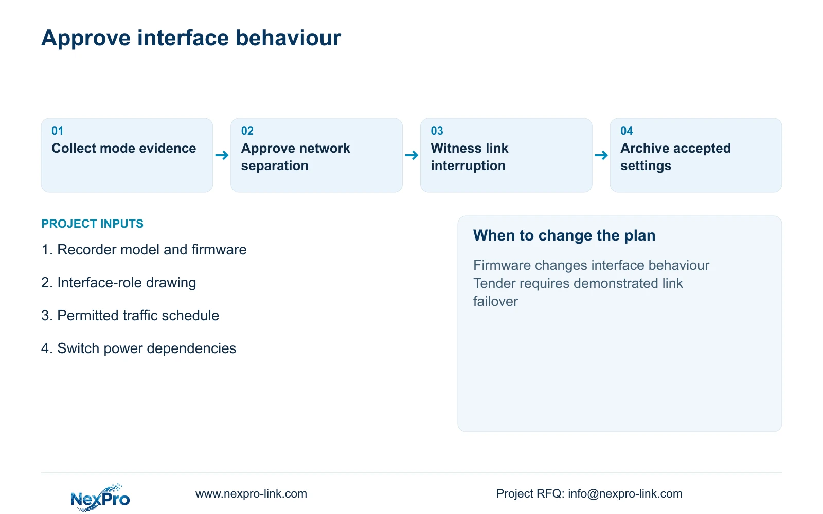
Prepare an approved test before commissioning. State the failed connection, the expected camera availability, the expected operator access and the evidence required afterward. The integrator should preserve the accepted configuration and establish baseline recording on all 32 channels before a controlled network interruption is introduced.
For a supported separated arrangement, loss of the viewing-side connection might leave camera ingestion intact. Verify that outcome through later playback of the test interval. Loss of the camera-side connection may have a very different effect. A live image returning afterward proves reconnection, but it does not prove that the interrupted interval was recorded or recovered.
Record observed interruptions rather than prescribing an unsupported recovery time. Include timestamps, channel identities, disk status and the steps needed to regain access. The network engineer owns the controlled link test; the integrator owns playback and export verification; the owner accepts the operational result. Do not conduct the test through an unapproved production-control connection.
Section 04
Keep access-group containment separate from dual-LAN claims
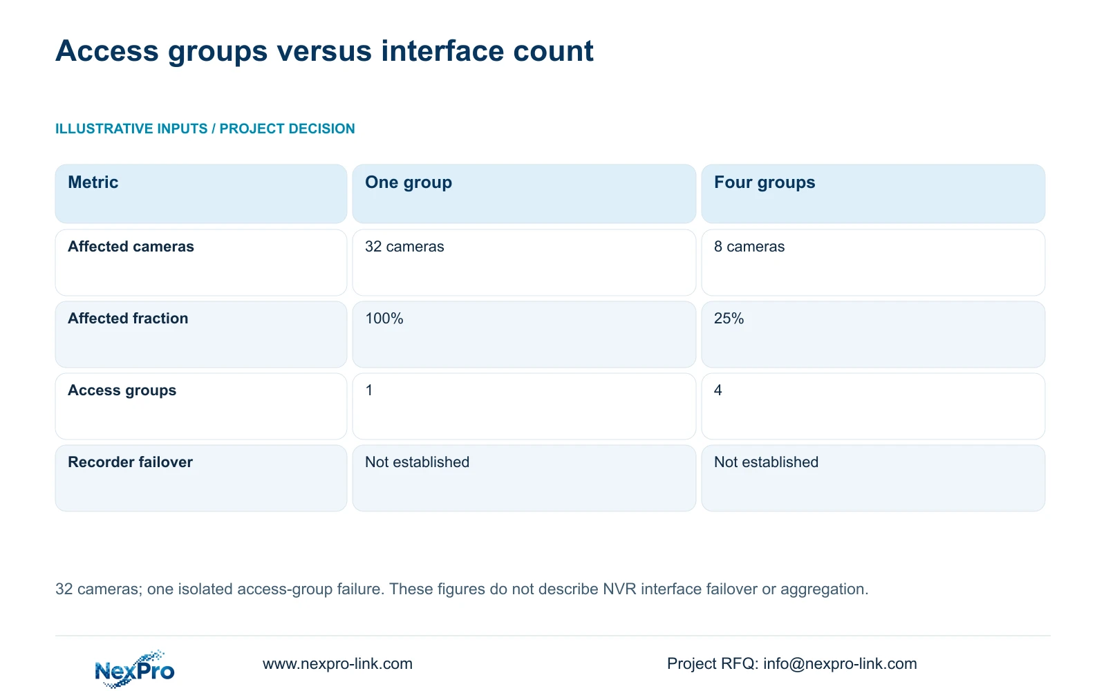
The supplied deterministic example compares 32 cameras in one common access group with four isolated groups of eight. Affected_endpoints = camera_count_in_failed_group; affected_fraction = affected_endpoints / 32. One group failure therefore affects 32 cameras, or 100%, in Option A and eight cameras, or 25%, in Option B.
This comparison concerns access-group boundaries, not the recorder's two sockets. Four groups can contain a local access failure when the remaining paths operate independently. They cannot prove a supported NVR failover mode, and two NVR interfaces cannot make one common access group into four independent groups.
CASE01's four PoE load groups provide a useful starting schedule, but the engineer must verify data-path independence separately. A common uplink or failed recorder may still interrupt all 32 streams. No failure probability, uptime percentage or automatic recorder recovery is derived from this table.
| Metric | Option A | Option B |
|---|---|---|
| Access groups | 1 common group | 4 isolated groups |
| Affected endpoints | 32 cameras | 8 cameras |
| Affected fraction | 100% | 25% |
| Automatic recorder failover | Not established | Not established |
Section 05
Approve a supported mode without overstating capacity
For this tender, approve dual LAN as a published hardware field while leaving aggregation and failover unapproved until exact supporting evidence is obtained. If documented separation meets the owner's task, specify that mode and its acceptance test. If continuity after an interface failure is mandatory, require demonstrated support or select another qualified architecture.
CASE01 assumes 32 streams averaging 4 Mbps, giving 128 Mbps of camera input. The NexPro-NVR4449-4K lists 320 Mbps input, four SATA bays up to 18 TB per drive and summary modes distinguishing 49×5MP from 9×4K. Keep those recording constraints separate from LAN link speed. Two Gigabit sockets do not establish a 2 Gbps recording limit or unrestricted 4K operation.
For mixed-brand devices, use the ONVIF Profiles reference to frame exact device, client and firmware checks. Basic video connection is only one workflow; event handling, search and audio may need separate tests. Compare bids against the same approved interface roles and retrieval requirements, including configuration and commissioning effort.
Section 06
Carry interface identity into the supply and handover records
The BOQ should state recorder identity and required network behaviour in separate fields. Add an interface schedule showing network role, addressing responsibility, permitted access and failure-test evidence. Mark existing switches as retained where appropriate, recorder configuration as supplied, and site routing changes as installer-provided unless the quotation explicitly includes them.
Include protected power on the dependency drawing. Even a supported alternative network path becomes unavailable if both switches lose their common supply. Record the generator arrangement and restart dependencies where they influence the acceptance test, without turning this network decision into a general UPS catalogue.
NexPro-Link's BOQ and tender support can help organise exact model matching, technical deviations and configuration requirements. Request those documents with the equipment offer. The handover pack should preserve the accepted firmware and settings so a replacement unit or later update does not silently change the approved network behaviour.
Section 07
Buyer questions
Can both NVR sockets connect to the same subnet? Only use an arrangement documented for the exact recorder and approved by the network designer. The supplied dual Gigabit LAN field does not settle addressing, routing or mode restrictions. Obtain the relevant interface documentation before defining that connection.
Does losing remote access mean recording has stopped? Not necessarily. A viewing-path failure can leave local camera ingestion and storage operating. Confirm the distinction with playback of footage recorded during the loss of access.
What evidence should accompany a failover claim? Require exact model and firmware support, the configured topology, a defined failure condition and recorded acceptance results. A photograph of two connected cables is insufficient.
Section 08
Clarify the recorder network requirement
Send the recorder model and firmware, proposed interface-role drawing, required failure behaviour and switch power arrangement to info@nexpro-link.com. NexPro-Link can discuss model evidence, tender deviations and a suitable verification scope.
Engineering references
These sources support the general planning principles. Always use the selected product's current datasheet and applicable project standards for final design.