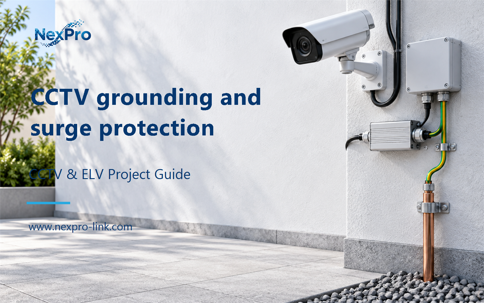
Plan CCTV grounding and surge protection with practical guidance on map conductive exposure paths and recognize the limits of protection. NexPro-Link project guide.
Section 01
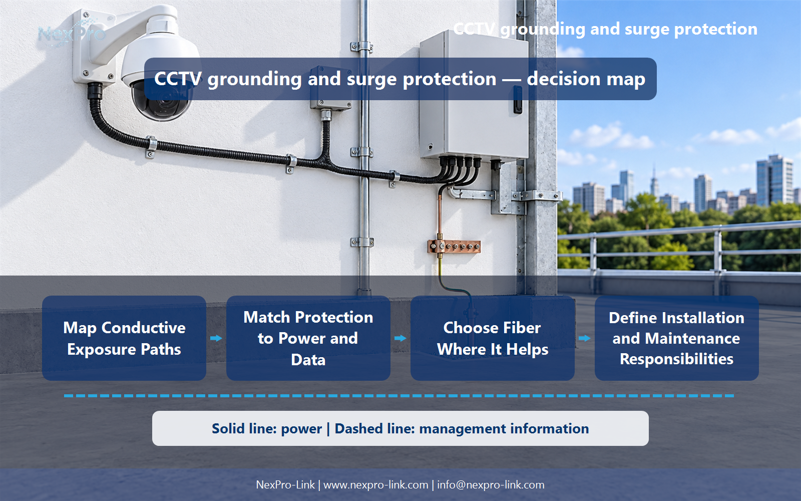
Map Conductive Exposure Paths
Potential paths include power, conductive data cables and connected metallic structures, depending on the site. Review the whole arrangement rather than protecting only the camera's Ethernet connector. Environmental exposure and the building's existing protective design shape the required measures.
Turn the answer into a working record using Path, Connected equipment, Exposure, Existing protection.
| Decision area | Buyer question | Required output |
|---|---|---|
| Map Conductive Exposure Paths | Where can surges enter a CCTV installation? | Potential paths include power, conductive data cables and connected metallic structures, depending on the site. |
| Coordinate Bonding and Earthing | Is an isolated ground rod always the answer for a camera pole? | No generic arrangement should be prescribed without the site electrical design. |
| Match Protection to Power and Data | Can any Ethernet surge protector be used on a PoE camera? | It must be suitable for the data application, PoE arrangement and installation conditions, as well as the coordinated protective design. |
Section 02
Coordinate Bonding and Earthing
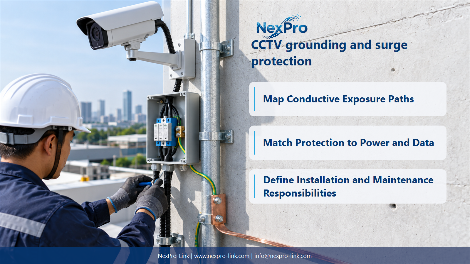
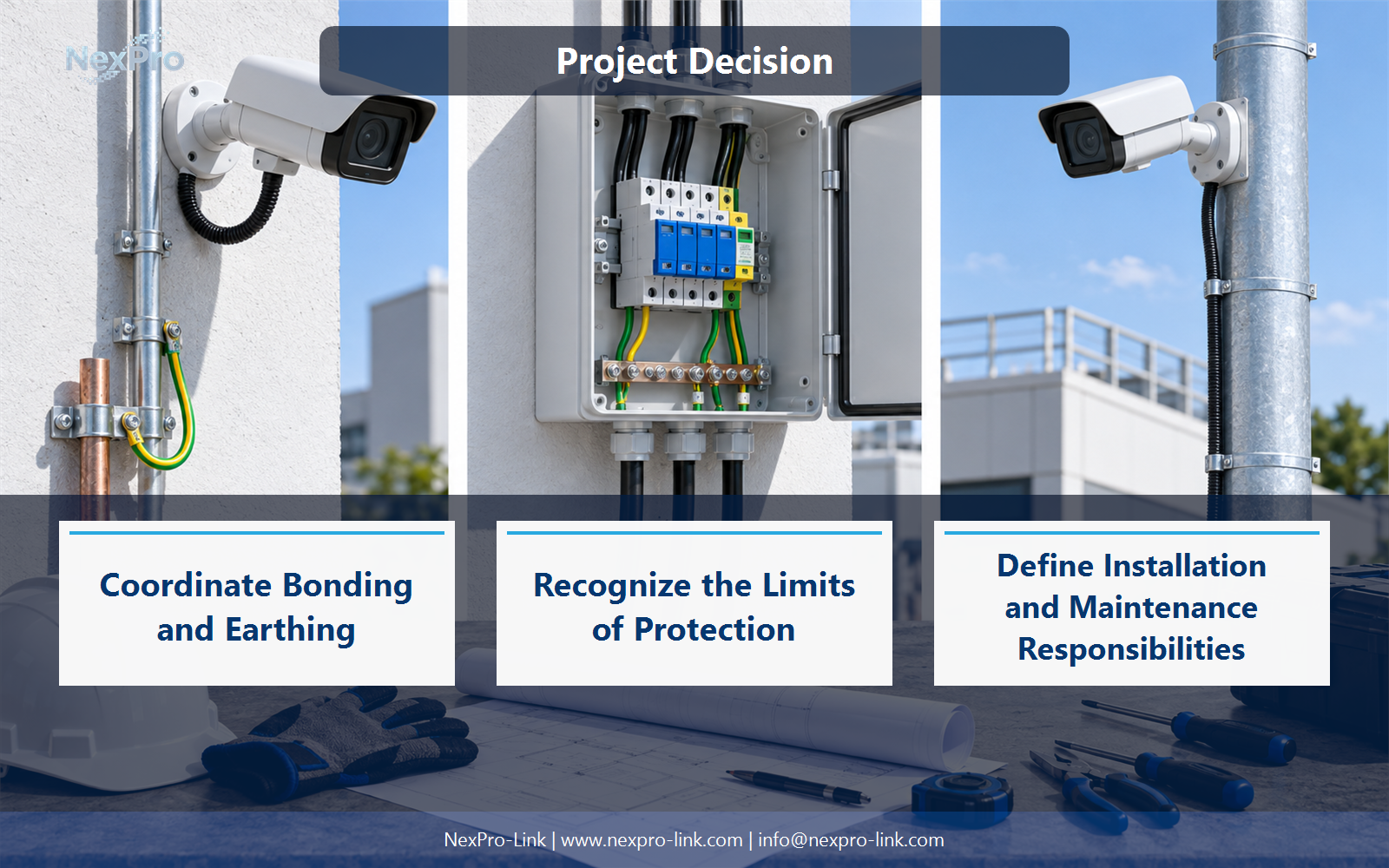
No generic arrangement should be prescribed without the site electrical design. Bonding and earthing must coordinate with the installation and applicable requirements to avoid harmful potential differences. Identify the responsible electrical specialist and use the site-specific bonding arrangement; a standalone ground rod is not a universal substitute for coordinated protection.
Use Structure, Bonding interface, Site design, Responsible party to compare options on the same basis. Keep product capability, project assumption and operating responsibility in separate columns.
Section 03
Match Protection to Power and Data
It must be suitable for the data application, PoE arrangement and installation conditions, as well as the coordinated protective design. An unsuitable device can impair communications or power delivery. Select it as part of the complete link rather than by connector appearance alone.
The project output should make Protector role, Data rate, PoE support, Installation traceable from input to acceptance.
- Confirm the answer to: Can any Ethernet surge protector be used on a PoE camera?
- Record the project fields: Protector role / Data rate / PoE support / Installation.
- Keep product capability, project assumptions and site responsibility in separate records.
Section 04
Recognize the Limits of Protection
No. Protective measures reduce specified risks within their design conditions; they do not guarantee survival of every event. Keep claims bounded and coordinate the installation. Equipment IP ratings describe enclosure protection and should not be presented as lightning or electrical-surge immunity.
Record Hazard, Protective role, Design condition, Remaining risk before selecting a product family. That makes later substitutions possible without silently changing the operational requirement.
Section 05
Choose Fiber Where It Helps
An appropriate optical link can remove a conductive data path between endpoints, but local power and metallic cable elements still need attention. Treat fiber as one architectural choice within the site design, not a substitute for all electrical protection and bonding requirements.
Review Link medium, Metallic elements, Local supply, Protection with the party that will operate or maintain the system.
Section 06
Define Installation and Maintenance Responsibilities
Identify who designs, supplies, installs and inspects the relevant protective and bonding components. Include accessible inspection and replacement arrangements where applicable. Do not imply that a camera supplier automatically provides or approves the site's complete lightning-protection system.
Use Task, Design owner, Supply, Installation, Inspection as the handoff between design and procurement.
Engineering references
These sources support the general planning principles. Always use the selected product's current datasheet and applicable project standards for final design.