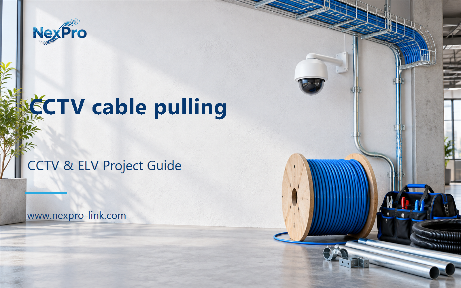
Plan CCTV cable pulling with practical guidance on plan pathways before pulling and coordinate power separation. NexPro-Link project guide.
Section 01
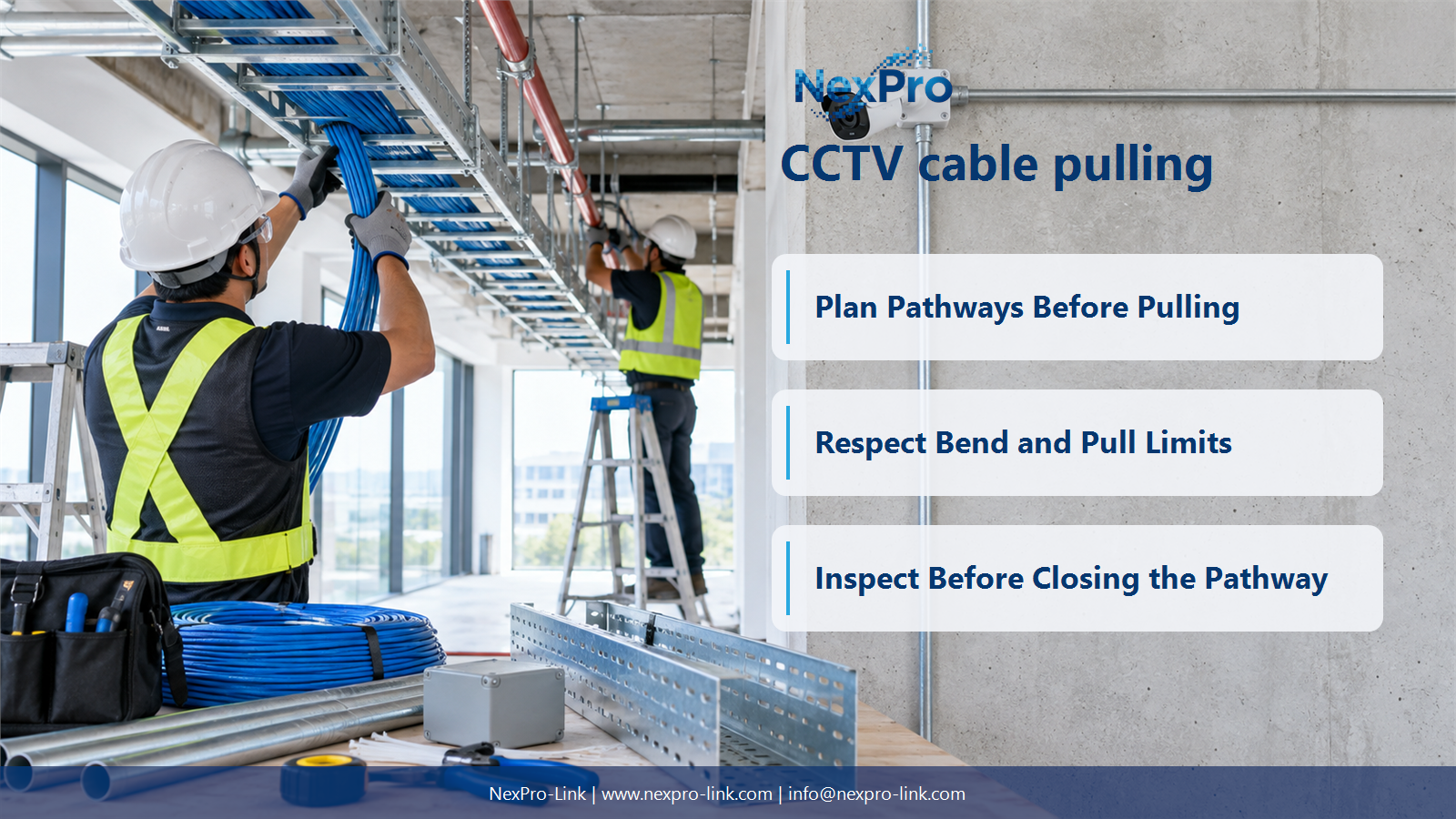
Plan Pathways Before Pulling
Confirm the approved route, access, supports, transitions and installation sequence with other trades. A cable that fits electrically can still be damaged or made inaccessible by a poor pathway. Resolve obstructed bends and shared-space conflicts before pulling the cable.
Turn the answer into a working record using Route, Access, Shared trade, Transition, Readiness.
| Decision area | Buyer question | Required output |
|---|---|---|
| Plan Pathways Before Pulling | What should be checked before CCTV cable pulling? | Confirm the approved route, access, supports, transitions and installation sequence with other trades. |
| Size Conduit and Tray Use | Is there one universal tray-fill percentage for CCTV? | No single value should be assumed for every pathway and jurisdiction. |
| Respect Bend and Pull Limits | Where should cable bend radius and pulling tension come from? | Use the cable manufacturer's installation guidance and the applicable installation requirements. |
Section 02
Size Conduit and Tray Use
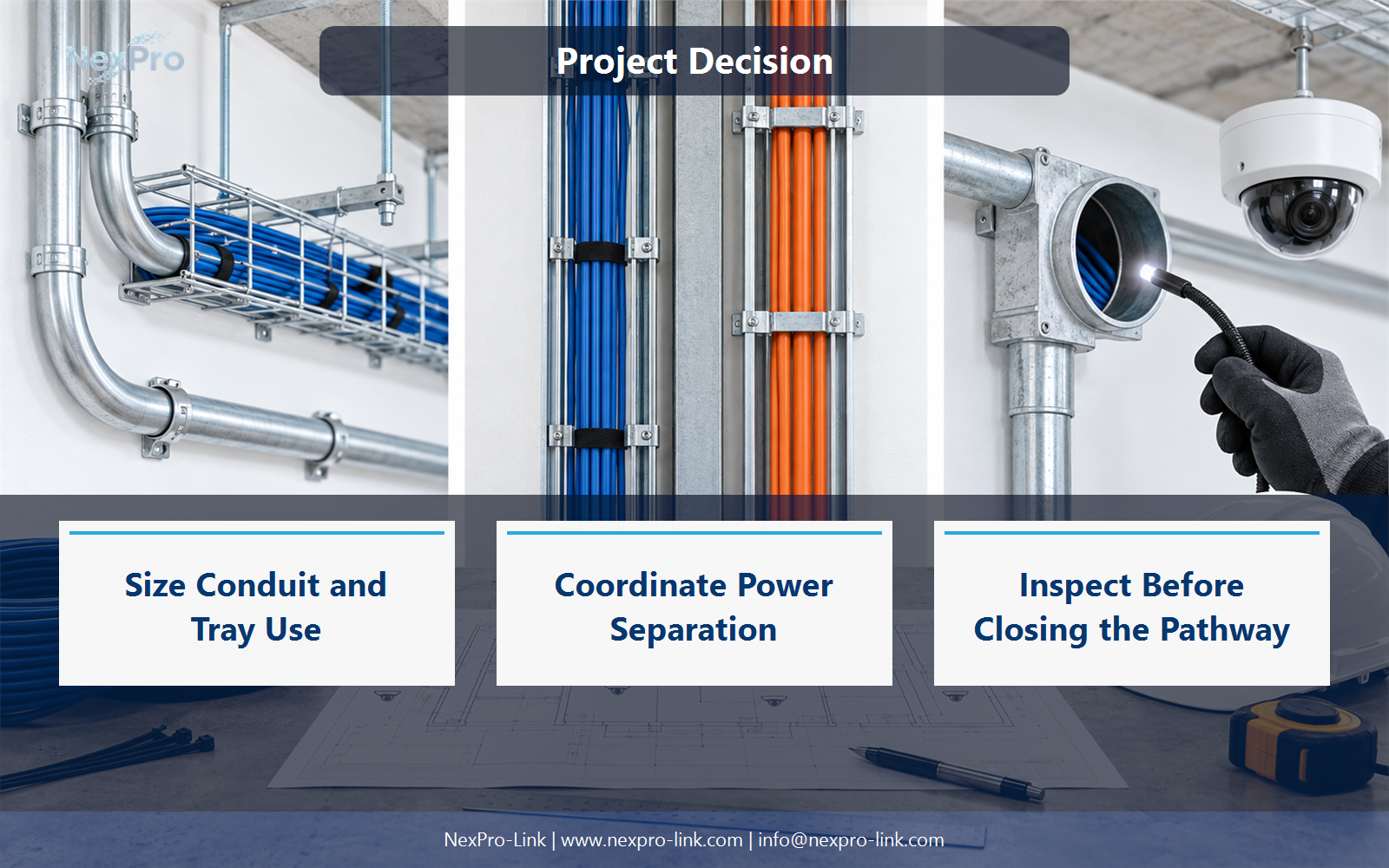
No single value should be assumed for every pathway and jurisdiction. Use the applicable pathway requirements, cable dimensions and installation conditions, including relevant thermal considerations for powered cabling. Keep space planning separate from a generic count of how many camera cables fit visually.
Use Pathway, Cable dimensions, Applicable fill, Reserved space to compare options on the same basis. Keep product capability, project assumption and operating responsibility in separate columns.
Section 03
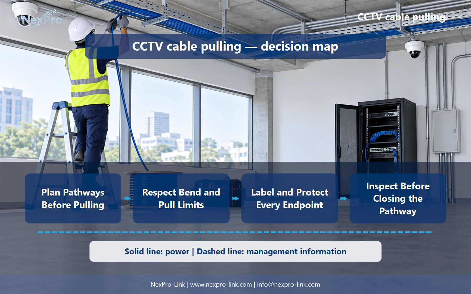
Respect Bend and Pull Limits
Use the cable manufacturer's installation guidance and the applicable installation requirements. Limits can differ with cable construction and whether the cable is under tension or installed. Avoid sharp bends, crushing and unsupported pulling methods that can affect the final link performance.
The project output should make Cable, Pull condition, Bend limit, Tension limit traceable from input to acceptance.
- Confirm the answer to: Where should cable bend radius and pulling tension come from?
- Record the project fields: Cable / Pull condition / Bend limit / Tension limit.
- Keep product capability, project assumptions and site responsibility in separate records.
Section 04
Coordinate Power Separation
The required arrangement depends on the applicable rules, power installation and pathway design. Coordinate with the responsible electrical team rather than publishing one distance as valid everywhere. Appropriate separation, crossing and bonding arrangements should be documented for the actual site.
Record Parallel route, Power context, Separation arrangement, Owner before selecting a product family. That makes later substitutions possible without silently changing the operational requirement.
Section 05
Label and Protect Every Endpoint
Label both ends during installation and keep the identifiers aligned with camera, patch-panel and switch schedules. Protect unfinished ends against damage and contamination. Waiting until every cable is terminated increases the risk of misidentification and unnecessary tracing work.
Review Cable ID, Camera, Patch port, Switch, Test reference with the party that will operate or maintain the system.
Section 06
Inspect Before Closing the Pathway
Confirm route completion, cable condition, identification and accessible service allowances. Resolve visible damage or routing conflicts before concealment. Final electrical testing remains necessary, but it does not replace inspection of supports and mechanical conditions that will become difficult to access.
Use Area, Mechanical condition, Labels, Access, Closure status as the handoff between design and procurement.
Engineering references
These sources support the general planning principles. Always use the selected product's current datasheet and applicable project standards for final design.