Build the power group around the continuous recording path, protecting more than the storage device alone. Plan the project from the camera aggregation topology, switch input loads and recording retention objective.
Section 01
Trace the Recording Path
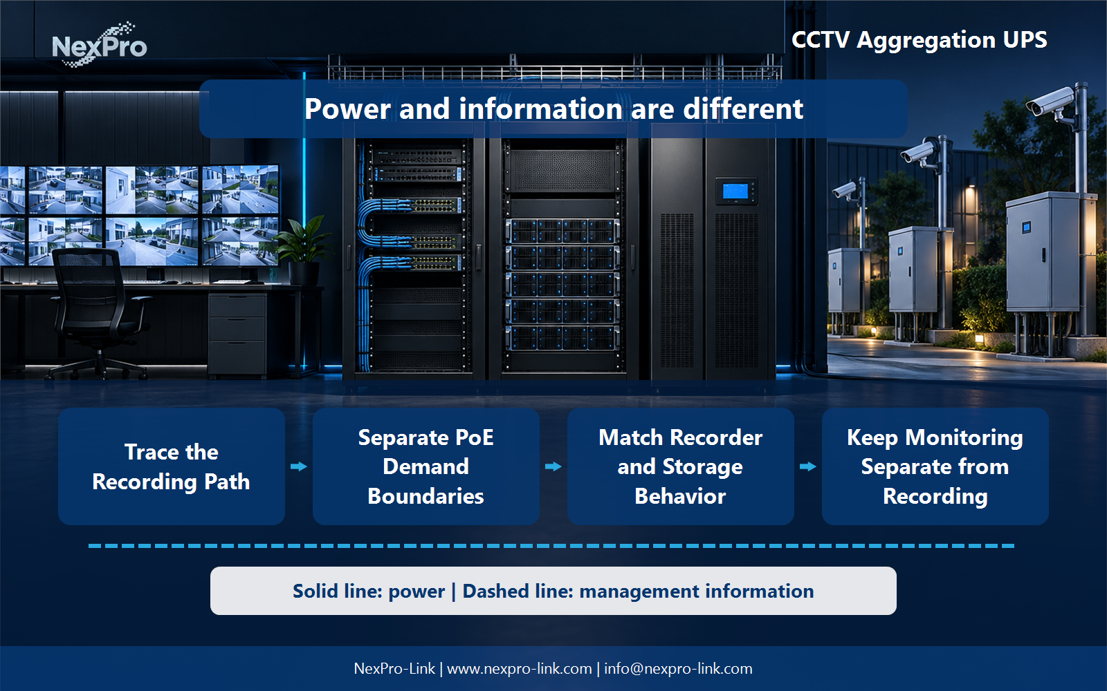
Build the power group around the continuous recording path, protecting more than the storage device alone.
Include the required camera supplies, aggregation links, recorders and storage. A powered NVR cannot record video that no longer reaches it. Draw the actual path and identify which front-end locations need independent backup.
Capture the answer in the recording path: camera power / access / aggregation / recorder / storage before equipment is compared. This gives the project team a concrete service target and exposes missing dependencies early.
| Decision area | Project question | Required output |
|---|---|---|
| Trace the Recording Path | What must remain powered for recording to continue? | Recording path: camera power / access / aggregation / recorder / storage |
| Separate PoE Demand Boundaries | How can camera power be counted correctly? | Demand table: measured input / endpoint estimate / switch overhead |
| Match Recorder and Storage Behavior | Does every NVR support automatic UPS shutdown? | Interface table: recorder / signal / supported action / fallback |
Section 02
Separate PoE Demand Boundaries
Use a consistent measurement boundary. If switch AC input already includes its PoE loads, do not add those cameras again. When estimating from endpoint demand, include the switch's own demand and clearly stated conversion assumptions.
Use the demand table: measured input / endpoint estimate / switch overhead to keep real interfaces and operating states visible. Measured demand, equipment limits and future allowances should remain separate entries.
Section 03
Match Recorder and Storage Behavior
No. Use the selected recorder's supported interfaces and operating procedure. Define what happens if direct shutdown integration is unavailable. For a project-specific decision, record recorder, signal, supported action and fallback in the interface table. This keeps the equipment inputs and intended service outcome aligned.
Review the interface table: recorder / signal / supported action / fallback with the owners of the connected systems. Power continuity only supports the functions that remain connected and available during the event.
- Confirm the answer to: Does every NVR support automatic UPS shutdown?
- Draw electrical power as a solid path and management information as a separate dashed path.
- Keep external services and specialist approvals outside the UPS equipment claim.
Section 04
Keep Monitoring Separate from Recording
Only when the operating objective requires it. Recording continuity and live viewing can have different priorities. Compare essential operator display with full-wall demand, and retain any management equipment required for a controlled recording stop.
Document this choice in the priority sheet: record / manage / essential view / full wall, including the condition that triggers it and the person responsible for the response.
Section 05
Test a Complete Service State
In an authorized test window, check video arrival, writing, retrieval and timestamps across the required event. A UPS self-test does not prove recording continuity. Record the scope and observed service result rather than claim a universal duration.
Test the sequence represented by the test map: power event / live stream / write / retrieve / time during an approved maintenance window. Record the observations needed to confirm recovery.
Section 06
Prepare an Aggregation RFQ
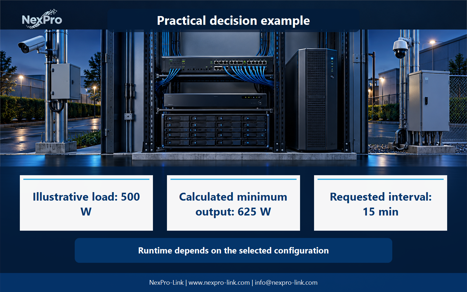
Provide network and power diagrams, recorder and storage loads, and the required recording behavior. NexPro-Link can discuss UPS and supporting equipment within that scope. Storage retention days and battery runtime should remain separate inputs.
Send the completed rfq schedule: path / load / recording goal / runtime / interfaces with the project request. It is more useful than a capacity number without interfaces, operating states or a defined service boundary.
Engineering references
These sources support the general planning principles. Always use the selected product's current datasheet and applicable project standards for final design.