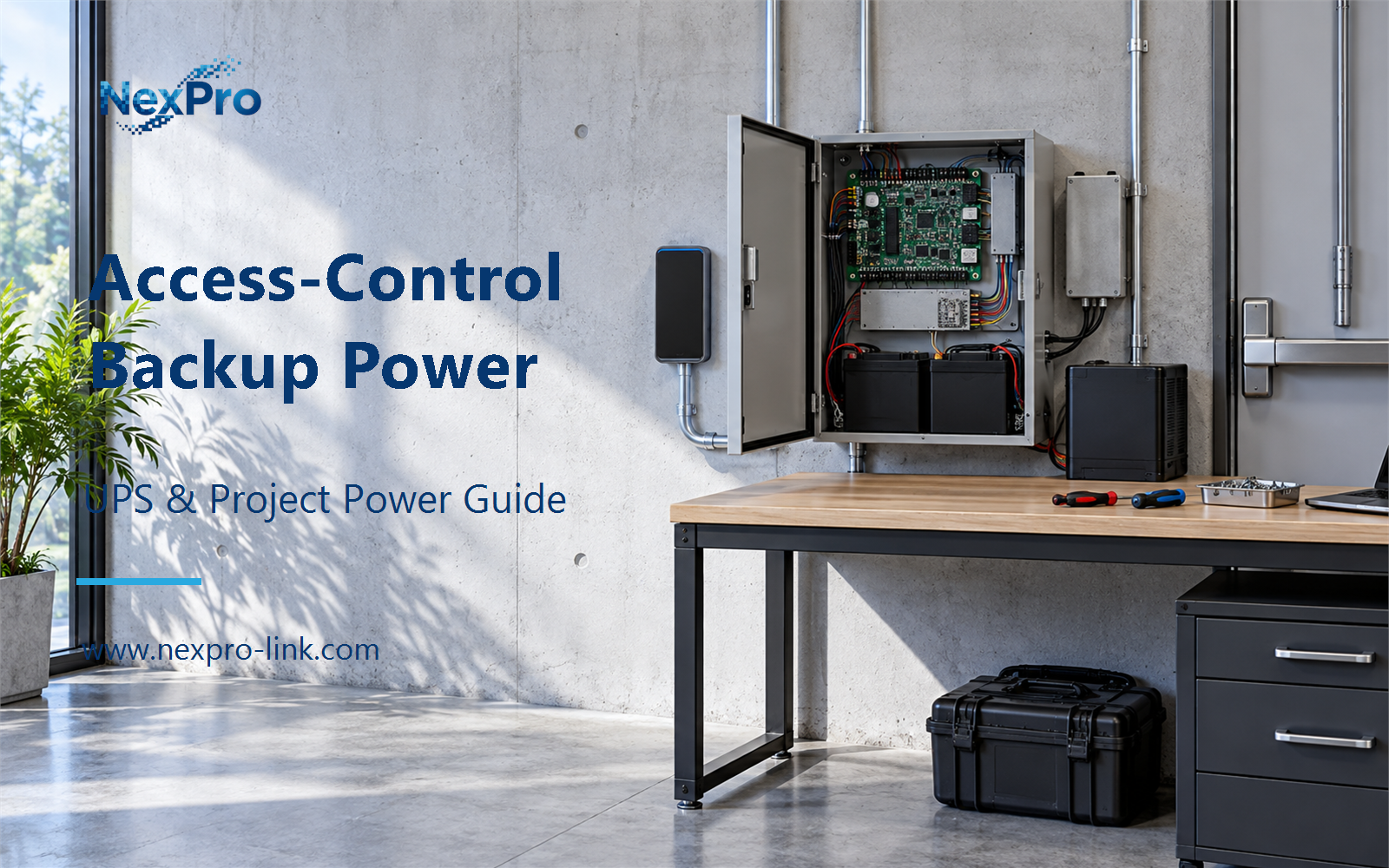
An access-control system looks like one load on a one-line diagram, but it breaks into several power consumers with different behavior.
Section 01
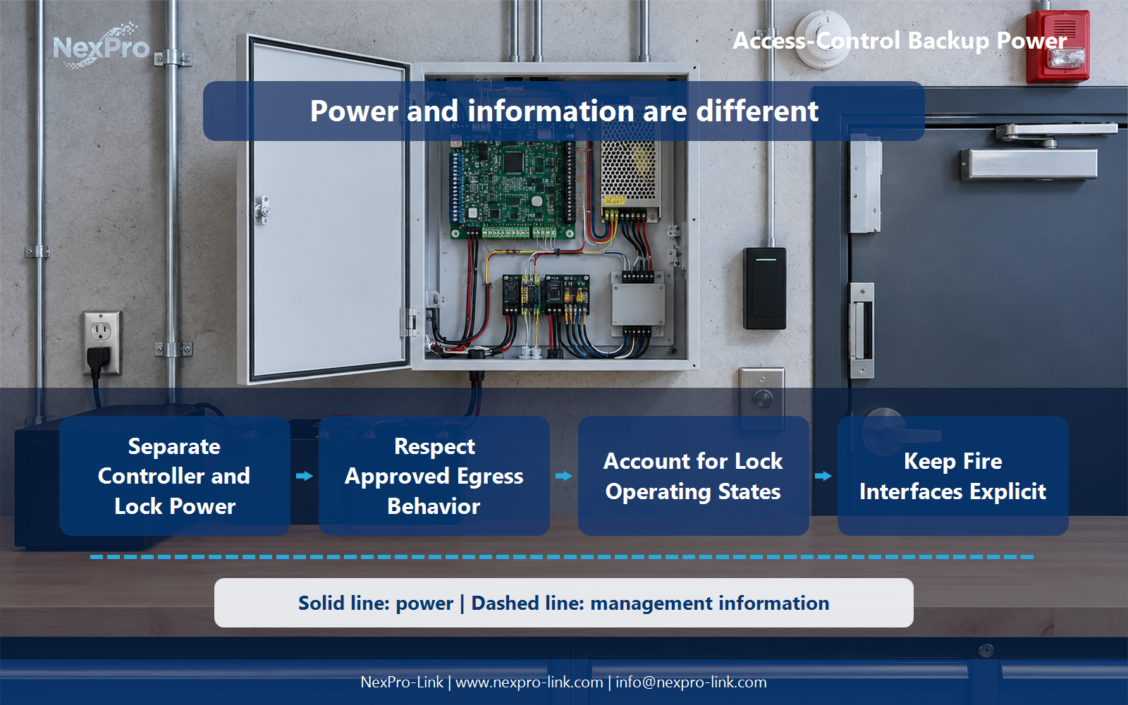
Separate Controller and Lock Power
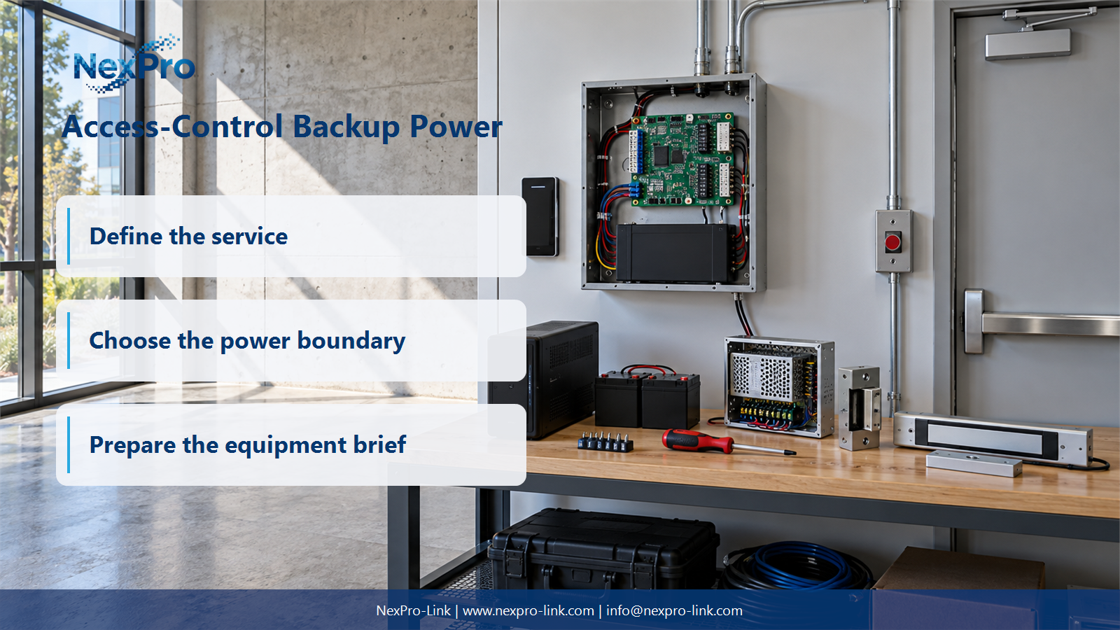
What belongs in an access-control power budget? Identify controllers, readers, locks and required networking, with their actual supply interfaces. They may not share the same power source. A generic UPS should not replace a specified access-control power supply or its protective functions without the approved system design. Access-control integrators and building MEP consultants can use that boundary to build the door-power map: controller / reader / lock / network / source and prepare approved door schedule, lock power requirements and egress interface specification before selection.
An access-control system looks like one load on a one-line diagram, but it breaks into several power consumers with different behavior. Controllers, readers, locks and the network that carries card decisions all draw current. Some need to stay online during an outage. Some need to release. A single UPS placed in front of the whole group can mix those two jobs together, and that is where a door schedule gets damaged. The backup supply has to serve the equipment without changing how a door behaves in an emergency.
The first step is to list every device and its supply interface before any battery sizing. A door controller might run from a 12 V DC access-control power supply. A reader might be powered from the controller's auxiliary output or from PoE on the network switch. A lock runs from a separate lock supply that often carries its own battery. The switch that connects the controller to the management software sits on building AC. These are four different boundaries.
The map makes the boundary visible. Controller power and lock power are separate decisions. If the lock supply drops, the lock responds according to its design. If the controller drops but the lock supply stays up, the door can remain secured while card decisions stop. A generic UPS does not know which of those outcomes the project approved, so it cannot replace the specified access-control supply and its protective functions on its own.
| Decision area | Project question | Required output |
|---|---|---|
| Separate Controller and Lock Power | What belongs in an access-control power budget? | Door-power map: controller / reader / lock / network / source |
| Respect Approved Egress Behavior | Should backup power keep every door locked? | Behavior table: door role / normal / outage / emergency / owner |
| Account for Lock Operating States | How should lock demand be calculated? | Lock schedule: type / input / hold / actuation / supply |
Section 02
Respect Approved Egress Behavior
Backup power should not keep every door locked. Door behavior comes from the egress, security and interface requirements written for that installation, and those requirements stay with the responsible design. The person sizing the UPS does not get to redraw them.
For each door, record its role, normal state, outage state, emergency state and owner.
The egress door is the case that catches mistakes. Its strike is fail-safe, so it releases when lock power drops. If a backup supply holds that strike energized through an outage, it keeps the door locked at the moment the door should be open for people leaving. The approved behavior says otherwise. The backup objective for that door is to keep the controller and network online so decisions and logs continue, not to hold the strike closed.
Section 03
Account for Lock Operating States
Lock demand cannot be read from a single current value. A strike draws one current while holding and a higher current for a moment when it actuates. A magnetic lock holds continuously at one level. Different lock types also run at different voltages. Applying one number to every lock overstates some circuits and understates others.
Use the selected lock's documented input and operating states.
The supply has to support the loads and protection arrangements the door design specifies, plus its total watt rating. Sizing for the holding current only can trip a supply or a fuse when several locks actuate at once. The lock schedule is the input that keeps those two states separate.
- Confirm the answer to: How should lock demand be calculated?
- Draw electrical power as a solid path and management information as a separate dashed path.
- Keep external services and specialist approvals outside the UPS equipment claim.
Section 04
Keep Fire Interfaces Explicit
A UPS must never be proposed as a way around an approved release signal. Fire interfaces release doors when the alarm system says so, and that action sits above the backup supply in priority. The interface has to be written down with the responsibility for each part.
The map keeps the power path and the release path from blurring together. Backup power supplies the controller so it can log the event and report the state change. The release itself happens through the fire interface, with or without battery power. That separation lets the system stay safe and stay monitored.
Section 05
Set the Correct Backup Objective
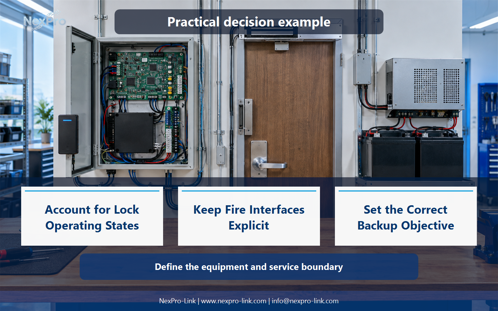
Backup time comes from the approved door and control-system requirements. Building type and the presence of a battery do not set the number. Controller communication and lock behavior are two separate objectives and belong on two lines.
For the illustrative scenario, the objective is to keep the controller, readers and network running for four hours while the egress doors release and the secure doors keep their approved state. Four hours is a teaching assumption, not a universal figure. The number should come from the door schedule and the local requirements, and it should be restated for controller communication and lock behavior separately.
Section 06
Prepare the Door-System RFQ
The last step is to hand the decisions to a supplier as inputs. NexPro-Link can discuss equipment supply within that scope. Door safety, egress and local compliance stay with the responsible system design, and a UPS product does not automatically provide them.
This package turns the six decisions into a comparable equipment discussion and gives the supplier the boundaries.
Engineering references
These sources support the general planning principles. Always use the selected product's current datasheet and applicable project standards for final design.