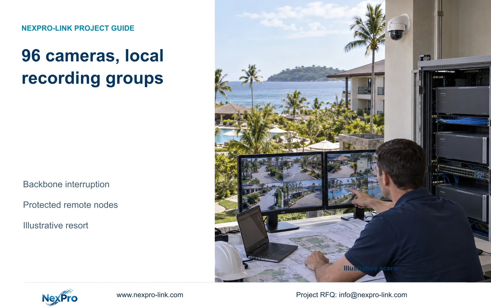
Three local recording groups preserve the illustrative resort's footage during a backbone interruption, provided every group's camera, network and power path remains operational.
Section 01
Group cameras around local recording boundaries
Choose local recording within each building group when footage must continue during an inter-building backbone interruption. Use the center for supported management and retrieval, while keeping each group's camera-to-recorder path operational without that backbone. Centralizing all recording is unsuitable for this objective unless another explicitly supported continuity arrangement meets it.
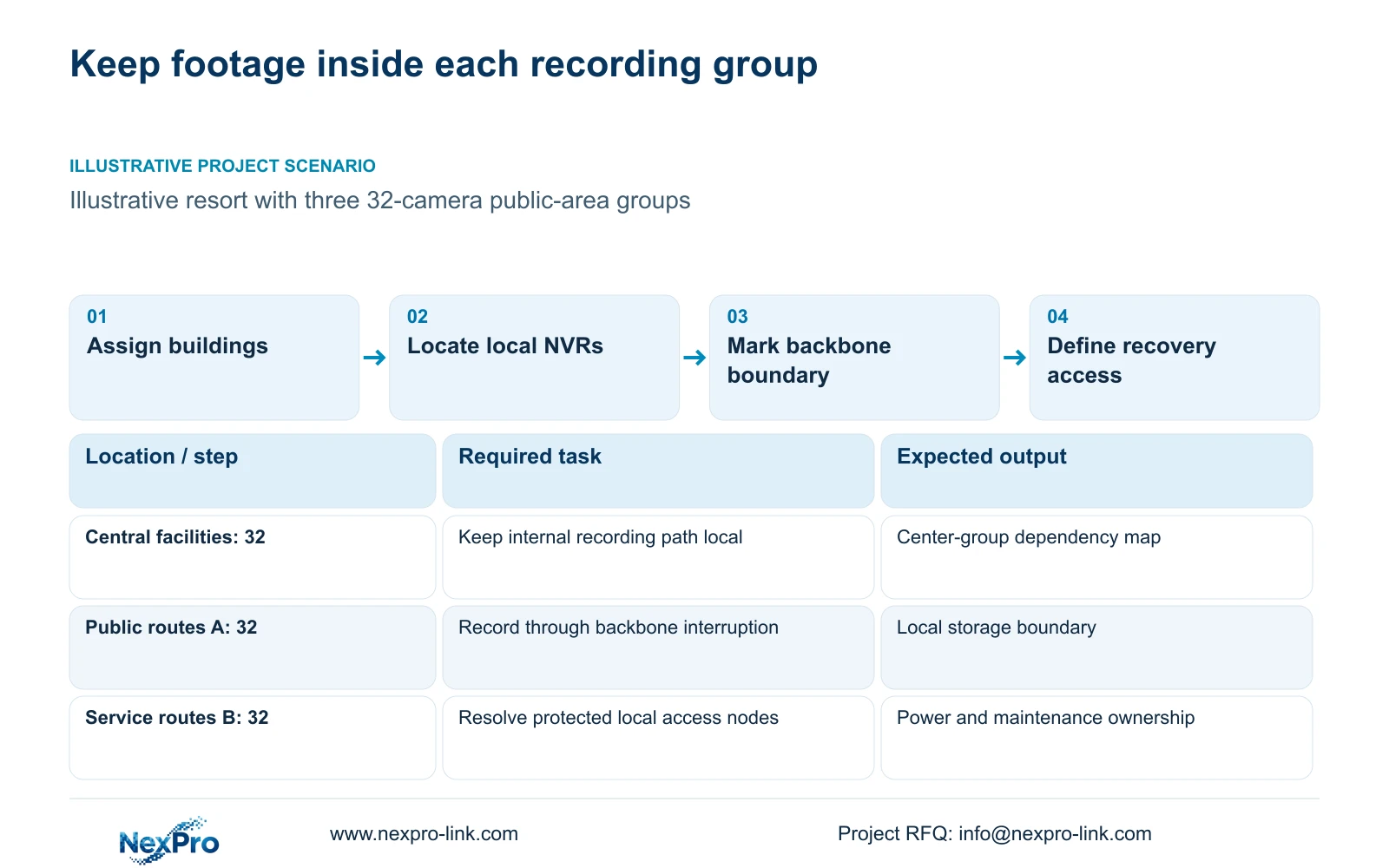
The illustrative CASE04 resort has 240 rooms and 96 public-area cameras arranged as three groups of 32. Reception and central facilities form one group; accommodation public routes form group A; accommodation and service routes form group B. These are task and network groupings, not a formula based on guest accommodation.
Draw the approved observation areas and local equipment locations together. Exclude private interiors and sensitive spaces. A group can include more than one building only if its internal recording path retains the intended failure boundary. Identify any link whose loss would separate its cameras from its recorder before accepting the group name as proof of independence.
| Group | Assigned cameras | Decision still needed |
|---|---|---|
| Reception and central facilities | 32 | Local recorder and internal paths |
| Accommodation public routes A | 32 | Building links inside the failure boundary |
| Accommodation and service routes B | 32 | Protected nodes and maintenance access |
Section 02
Specify what remains available during backbone loss
The required state is continued local capture and recording. Central viewing can become unavailable while local storage continues, so acceptance must distinguish those outcomes. Specify whether an authorized local operator also needs playback during the interruption, and how central staff regain access after the link returns.
CASE04 examines three NexPro-NVR4449-4K units, one for each 32-camera group. The public record lists 49 channels, 320 Mbps input and four SATA bays. Its summary identifies 49 × 5MP and 9 × 4K; those fields do not authorize every mixed-resolution combination. Keep exact camera modes and drive configuration attached to each recorder.
A useful continuity demonstration observes recording through the agreed interruption, then retrieves the relevant interval. No such result is supplied here. A powered recorder cannot prove continuity if cameras lose PoE or their local switch requires an unavailable upstream service. Likewise, coordinated equipment supply does not establish automatic central-client compatibility or automatic copying of stored footage after reconnection.
Section 03
Calculate storage locally and traffic on actual links
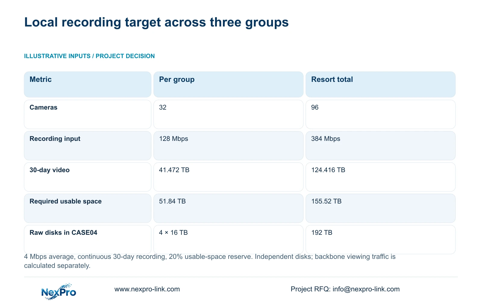
The topic calculation assumes 96 cameras averaging 4 Mbps, operating continuously for 30 days. Total recording input is 96 × 4 = 384 Mbps. Decimal video volume is 0.0108 × 96 × 4 × 30 = 124.416 TB. Keeping 20% of usable space free requires 155.52 TB. Both equipment options retain this target.
Each 32-camera group therefore receives 128 Mbps and needs 41.472 TB of video space, or 51.84 TB usable with reserve. CASE04 assigns four 16 TB drives per recorder. Across three units, 192 TB raw becomes 182.4 TB under the assumed 95% formatting allowance. The remaining video budget after reserve is 145.92 TB, corresponding to 35.19 planning days. This independent-disk example includes no RAID loss.
The resort's 384 Mbps total does not establish inter-building backbone traffic. If streams terminate at local recorders, central live viewing and exports determine the traffic leaving those groups. Each of the case's six 16-camera access nodes carries 64 Mbps pure recording traffic, or 70.4 Mbps with its illustrative 10% allowance, on the path to its local recorder. Count central requests only where they actually travel.
| Metric or condition | Essential local package A | Enhanced package B |
|---|---|---|
| Aggregate recording input | 384 Mbps | 384 Mbps |
| 30-day video data | 124.416 TB | 124.416 TB |
| Required usable capacity | 155.52 TB | 155.52 TB |
| Protected path | Cameras, local network and recording | Same plus selected extras |
| Operator display | Task-sized monitor/workstation | Optional wall; independent recording |
| Cost comparison | Complete local-package quote | Documented additions |
Section 04
Provide protected power at every active node
Fiber carries data between buildings; it does not automatically supply the remote switches or cameras. Identify AC availability and backup responsibility at each active node. Adding an extender or intermediate switch also adds a service and power dependency, which belongs inside the continuity assessment.
CASE04 uses six nodes with sixteen cameras each. At an assumed 12 W device peak, each group needs 192 W at the cameras. With 90% delivery, required switch output is 213.33 W. Retaining 20% spare raises the budget to 266.67 W per node. These CASE04 groups differ from the topic library's eight-camera PoE illustration and must not inherit its smaller budget.
NexPro SW-POE1618G remains provisional because total PoE watts are absent and access-speed descriptions conflict. The case's assumed 92% conversion efficiency and 20 W own consumption yield 1,511.3 W across access nodes. Adding three recorders, core and ordinary screen gives 1,751.3 W and 1,945.89 VA at PF 0.9. SP3KR(S) is only an aggregate capacity candidate; separate buildings require locally sized protection. The 1,216.18 Wh teaching estimate for 30 minutes does not establish actual batteries or runtime.
Section 05
Compare central management with distributed maintenance
Local recording reduces dependence on the inter-building backbone for storage, while increasing the number of equipment locations to maintain. Assign ownership of configuration records, disks and access permissions for each group. Operators need a known retrieval route when central access is unavailable, followed by a supported workflow after restoration.
Confirm live view, cross-group search, playback and export against the actual client and versions. ONVIF profiles are a relevant compatibility starting point, not evidence of all management functions. Price any platform, server or license scope explicitly rather than treating remote access as unlimited cloud storage.
A center display upgrade can improve shared observation without changing local retention. CASE04's optional LCD wall and decoder add an assumed 580 W, taking the aggregate load to 2,331.3 W and 2,590.34 VA. That exceeds the case's 20% reserve target on the stated 3 kVA/2700 W rack rating. Split protected zones or seek a larger supported configuration if that display must be backed up. Keep local recording unchanged while evaluating the extra cost.
Section 06
Issue packages by building group and cable endpoint
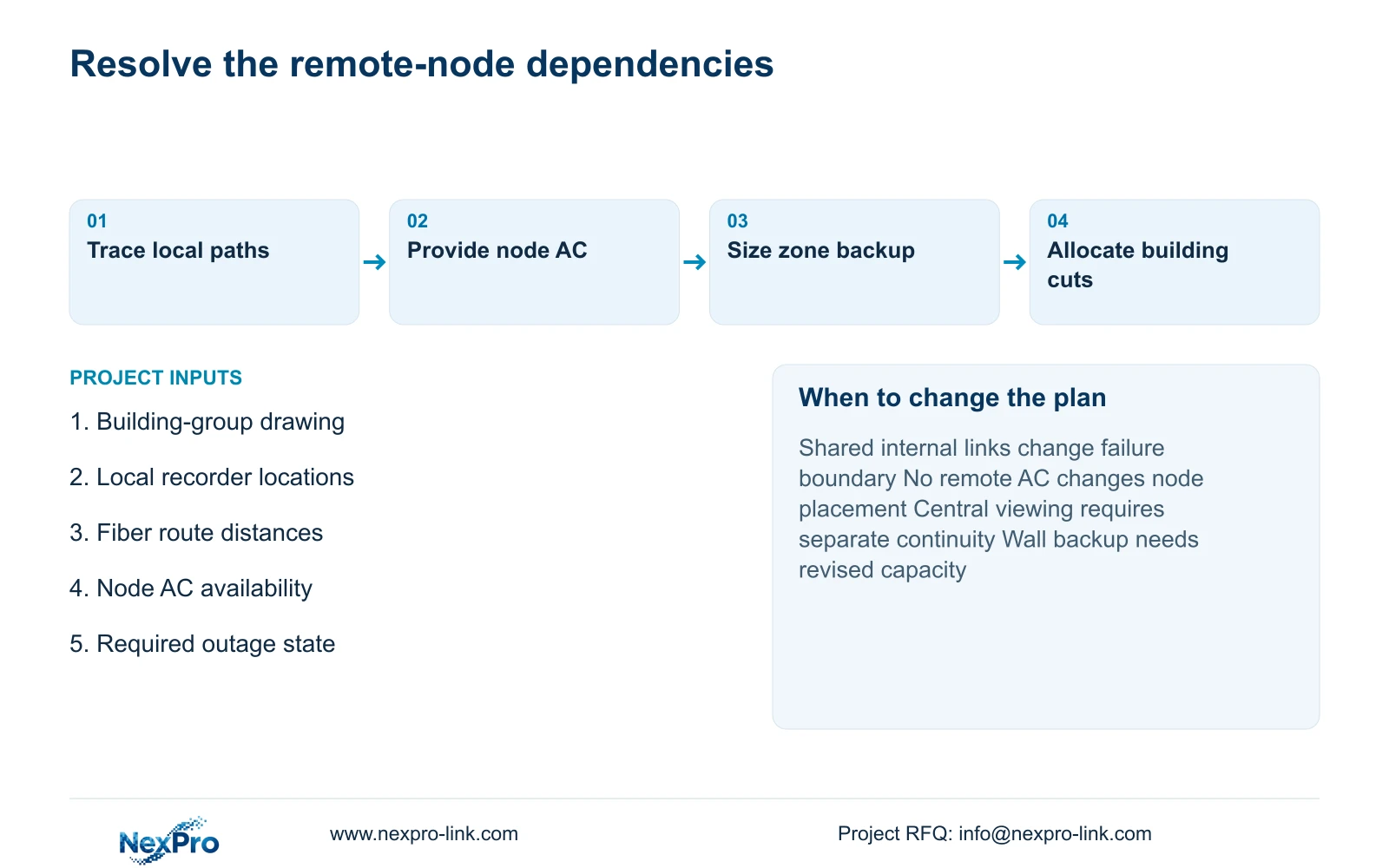
Recommend the three local groups when the site confirms their independent internal paths, protected power and required operating modes. Change the grouping if actual building links create a shared recording dependency. Each package should identify cameras, recorder and drives, access-node outputs, UPS location and the backbone interface.
CASE04's 96 continuous copper routes total 5,548 m. Its feasible 19-reel plan uses 305 m reels and leaves 247 m in distributed tails. This aggregate plan is not a building-by-building delivery allocation; split actual cuts and reels by installation sequence. Typical copper planning distinguishes the 90 m permanent-link basis from a 100 m channel including patch cords, with project-specific category and test requirements.
Use SP5648 and DT968MX only as their documented patching roles. Specify bulk cable, fiber routes and associated interfaces separately. Send the building-group plan, recorder locations, inter-building distances and outage target to info@nexpro-link.com, with destination. NexPro-Link can discuss BOQ and supply coordination; local electrical and installation duties remain explicit. The supplied 24-month main-equipment baseline from receipt does not automatically cover batteries, disks or cable on identical terms.
Section 07
Buyer questions
Will central viewing remain available when the backbone fails? It may not. Local recording and central viewing have different paths. If both must continue, specify the additional supported network and management arrangements instead of assuming local storage preserves center access.
Does local recording eliminate backbone capacity planning? No. Simultaneous viewing, replay and exports still use inter-building links. Size those paths from actual central tasks, even when routine recording stays within each group.
Can the overall cable reel count be used for each building order? No. Allocate continuous endpoint cuts to each delivery package and installation phase. Aggregate tails cannot be treated as one usable cable or assumed transferable between crews.
Engineering references
These sources support the general planning principles. Always use the selected product's current datasheet and applicable project standards for final design.