Separate SCADA, PLC and network power from pump power and safety controls. Plan the project from the control and communications loads, pump-power exclusions and outage response requirements.
Section 01
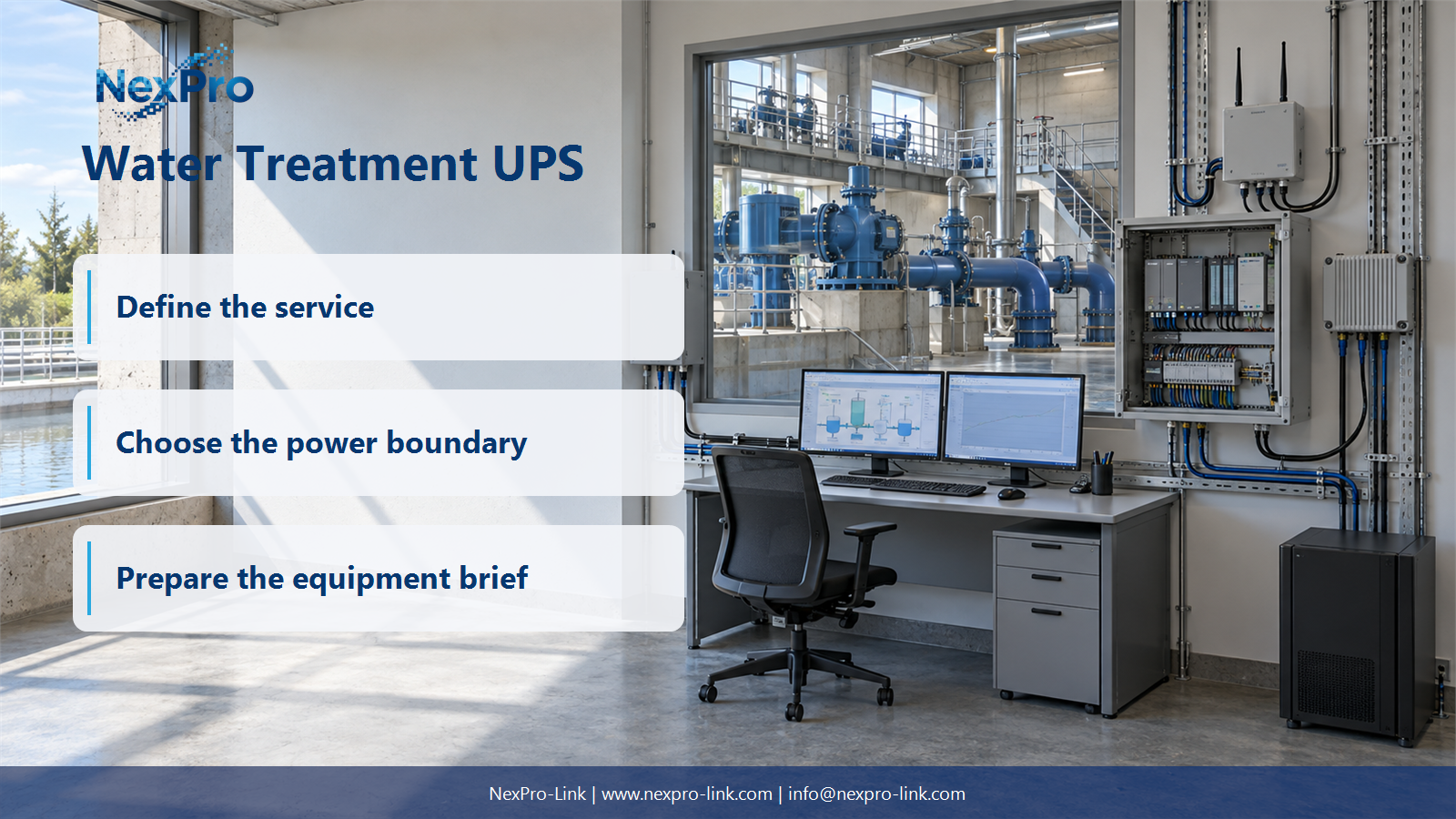
Separate Control and Pump Power
Separate SCADA, PLC and network power from pump power and safety controls.
The first decision is where the electrical boundary sits. On one side are the devices that keep the operator informed and keep the process logic running. On the other are the devices that do the physical work. Treating them as one load hides what must stay alive for a defined interval and what is deliberately stopped.
Motors draw a starting current well above their running current. Drives and soft starters shape that current and add their own control and rectifier losses. If a pump were added to the control group, its starting current would dominate the load calculation and pull the battery down faster than the control electronics ever required. The control group would then be sized around the wrong event.
The process design also matters here. Some plants stop certain pumps the moment utility power drops. Others let a pump run down in a controlled sequence. Either way, the approved operation and stopping behavior come from the process and safety design, not from the UPS. The UPS only has to keep the control side available while those decisions are carried out.
The table scopes the boundary. It is not a wiring diagram. Each "yes" still needs its own supply path and its own measured input before it enters the load schedule.
| Decision area | Project question | Required output |
|---|---|---|
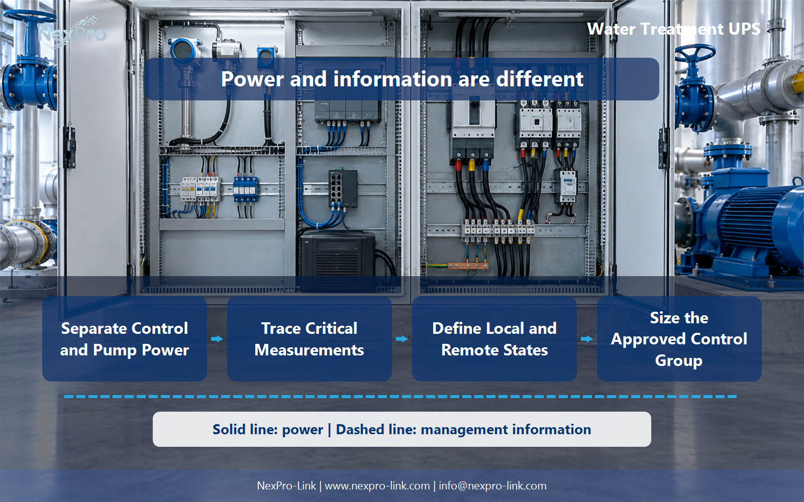
| Separate Control and Pump Power | Should a control UPS carry treatment pumps? | Scope table: PLC / network / sensors / drives / pumps |
| Trace Critical Measurements | What monitoring should remain available? | Measurement map: sensor / control / communication / operator |
| Define Local and Remote States | What happens if the remote link fails? | State table: source / local control / link / reporting |
Section 02
Trace Critical Measurements
Once the boundary is set, the next question is which measurements and communications the operator needs during the outage. The aim is a short list. Keeping the control side powered does not allow an unsafe process to continue, and it does not guarantee treatment performance. It keeps the operator able to see what is happening.
Begin with the measurements that describe the process state: tank or well level, flow, pressure, pump status and any alarm conditions the operator must act on. For each one, write down two dependencies. The supply dependency asks where the instrument gets its power. The data dependency asks where the signal travels and where it is recorded.
A level transmitter fed from the control panel dies with the panel unless that panel is on the UPS. A transmitter fed from a separate field loop needs that loop accounted for too. A reading that reaches the PLC but never leaves the site is visible only on site. Missing either dependency turns a "protected" measurement into a gap that only shows up during the outage.
Visibility supports the operator. It does not replace the process and safety decisions that stay with the plant's responsible people.
Section 03
Define Local and Remote States
Power loss and telemetry loss are different events, and they often arrive together. The plant needs a defined answer for each combination. When the remote link fails but power is present, the local controller should keep running its approved logic and the site should keep operating on local control. Repeated remote power cycles are not a sensible response to missing telemetry. They risk interrupting a process that was running correctly on site.
The state table below records source, local control, link and reporting for the states that matter. Fill it with the plant's approved behavior before the UPS is sized, because the reporting path is part of what the UPS protects.
Keeping the link on the UPS only makes sense if the site actually uses remote visibility during an outage. If the response is always local, the gateway may still need power for later records, and the operator should confirm that need.
- Confirm the answer to: What happens if the remote link fails?
- Draw electrical power as a solid path and management information as a separate dashed path.
- Keep external services and specialist approvals outside the UPS equipment claim.
Section 04
Size the Approved Control Group
Sizing counts only the devices needed for the defined control and monitoring state. Include any auxiliary load that is explicitly approved. Keep motor start and pump power out of the calculation, and do not hide them inside a general capacity margin.
The load schedule starts from compatible input figures. For each device, list its input in watts, its normal draw and its peak draw. In this teaching example the three devices are shown at the same normal and peak values. Real equipment may have startup or inrush figures that must be entered separately.
The watts and the volt-amperes are checked separately. A device list in watts alone can understate the apparent power when the power factor sits below 1.0. The worked example in the next section shows the arithmetic.
Section 05
Coordinate Restart and Records
UPS recovery is only an electrical observation. When utility power returns and the UPS goes back on line, the control group has power again. That says nothing about whether the plant is ready to resume treatment.
The facilities and process owners each confirm their own conditions using approved procedures. The electrical team confirms the source is stable and the UPS output is healthy. The automation or process team reviews the control state, setpoints and alarms. The SCADA team checks that telemetry and history are complete across the gap. Only then does the process authority clear the plant to resume its intended operation.
If the supported monitoring service is treated as restored before these steps finish, a gap the UPS was never meant to close can go unnoticed.
Section 06
Prepare the Water-Site RFQ
The equipment discussion starts from a short brief. NexPro-Link needs the control-device list, the source interfaces, the environment and the continuity objective. Pump systems, treatment quality and process-safety decisions stay outside any general backup-power claim.
This brief lets NexPro-Link match a UPS configuration to the boundary the project has defined. It also keeps the discussion honest: the supplier proposes equipment for the control group, while the specialist system design and application behavior stay with the responsible parties.
Engineering references
These sources support the general planning principles. Always use the selected product's current datasheet and applicable project standards for final design.