Tier addresses facility performance conditions; no single UPS or 2N label grants a level. Plan the project from the facility performance objective, power-path architecture and equipment-supply boundary.
Section 01
Identify the Object of Classification
Tier addresses facility performance conditions; no single UPS or 2N label grants a level.
The question "Is a UPS itself certified as a Tier III or Tier IV data center?" has a short answer: no. The classification concerns the data-center infrastructure and the criteria the Uptime Institute applies to it. A UPS nameplate describes ratings, topology, and battery configuration. It says nothing about the room, the cooling plant, the generator, or the distribution that carries power from the UPS to the load. Those sit inside the facility boundary and outside the product boundary.
For a project, the clean way to hold this distinction is an object table with four columns: UPS, distribution, facility, and evaluation scope. Each column names what it covers and what it cannot establish. Filling the table before equipment selection keeps the equipment inputs matched to the intended service outcome.
The table reads left to right as a chain. The UPS ends at its output terminals. Distribution picks up there. The facility wraps around both. The evaluation scope sits over the whole site, so no single row produces a Tier level.
| Decision area | Project question | Required output |
|---|---|---|
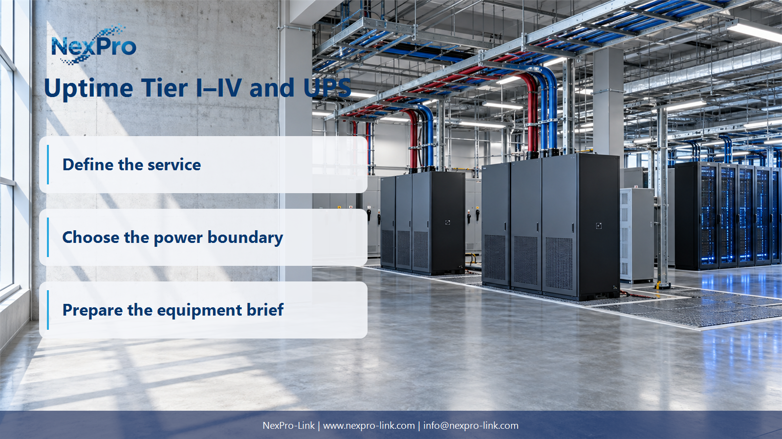
| Identify the Object of Classification | Is a UPS itself certified as a Tier III or Tier IV data center? | Object table: UPS / distribution / facility / evaluation scope |
| Explain the Progression Carefully | How do the Tier levels differ at a high level? | Concept table: level / general objective / facility boundary |
| Separate Redundancy Labels from Outcomes | Does N+1 or 2N automatically establish a Tier level? | Outcome map: capacity / paths / maintenance / fault condition |
Section 02
Explain the Progression Carefully
The four Tier levels move from a basic single path toward redundant capacity, concurrent maintainability, and fault tolerance. Each level describes a facility objective, and that objective reaches across the whole site. A count of UPS units does not reveal the level on its own.
These rows are a high-level orientation. A formal design or evaluation uses the current Uptime Institute criteria for the defined infrastructure. Two points follow for a UPS conversation. A Tier objective is a facility objective. A UPS selection supports that objective without inheriting its label. A Tier III objective may require power paths that stay usable during planned maintenance; the UPS is one part of that, while distribution, cooling, and the generator arrangements carry the rest.
Section 03
Separate Redundancy Labels from Outcomes
N+1 and 2N describe capacity and path arrangements. They do not establish a Tier level. A project can install two UPS systems and still share a utility intake, a cooling plant, or a downstream busbar. Any shared point reduces what the redundancy actually buys.
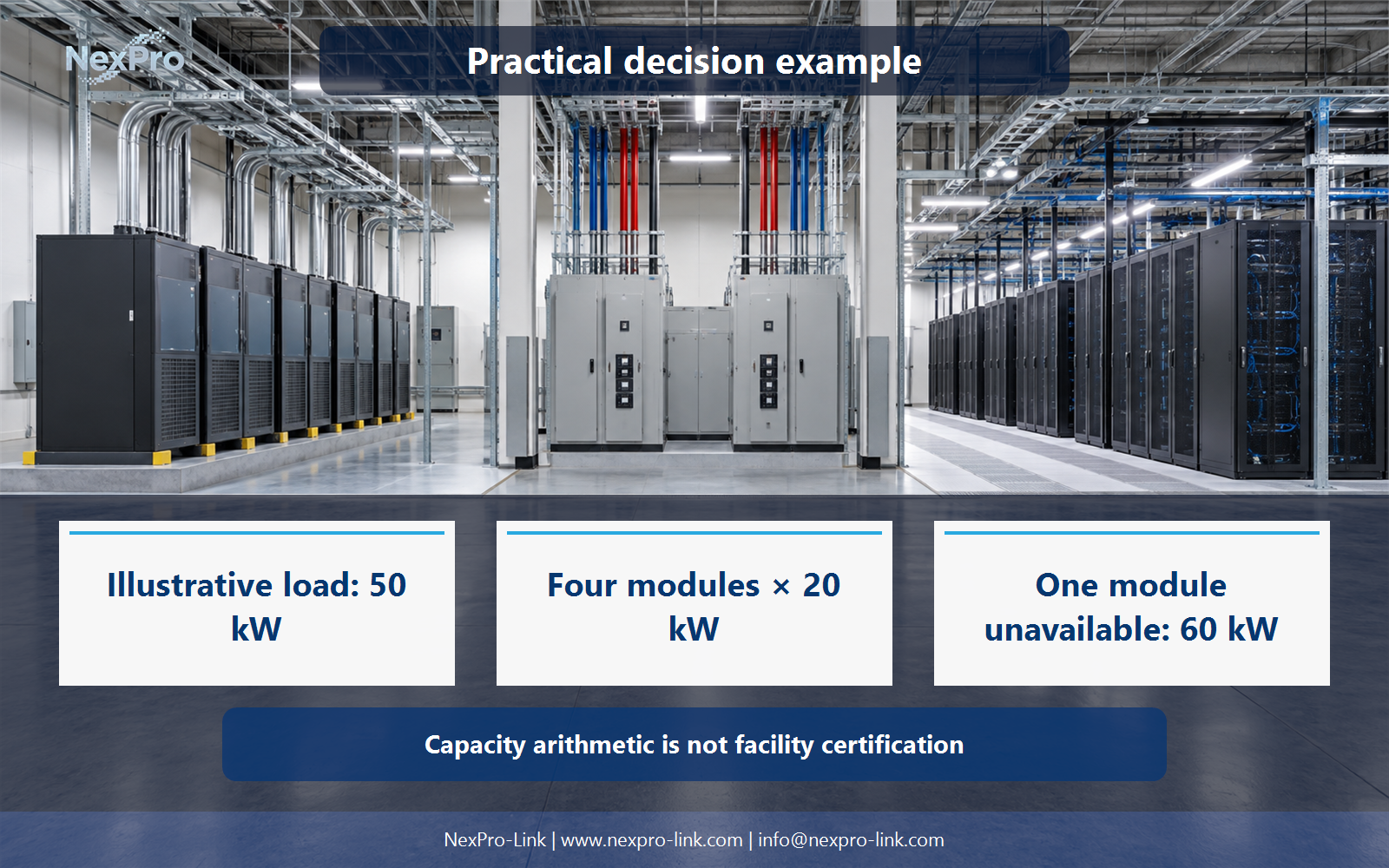
Both arrangements land at 60 kW of surviving capacity in this teaching example. The load, set at 50 kW, stays covered in either case on paper. The Tier question lives elsewhere: whether the paths stay usable through a nominated fault, whether maintenance can proceed without dropping load, and whether the shared points have been traced. Compare the intended performance outcome. A module count or a dual-system label is not a complete facility classification.
- Confirm the answer to: Does N+1 or 2N automatically establish a Tier level?
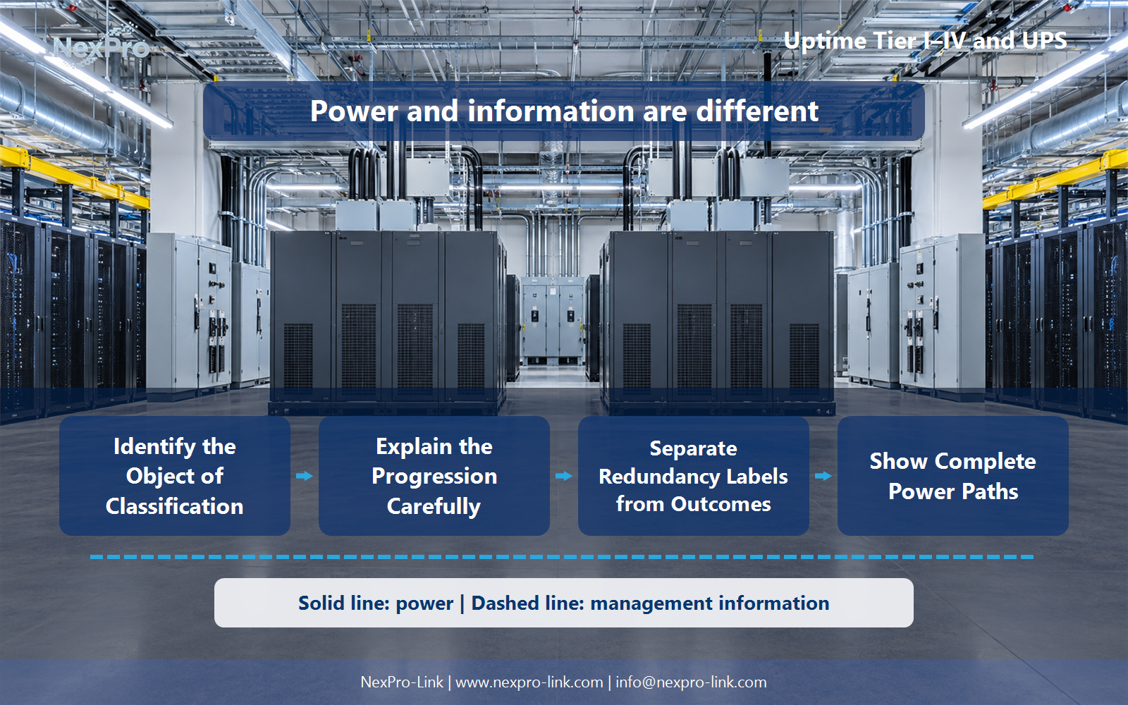
- Draw electrical power as a solid path and management information as a separate dashed path.
- Keep external services and specialist approvals outside the UPS equipment claim.
Section 04
Show Complete Power Paths
A useful diagram traces every source through the UPS, the distribution, and the load connections, and marks each point where two paths share something. Two UPS symbols do not prove two independent usable paths. The drawing has to show the first common point, such as the utility transformer, and the operating states the facility objective requires.
The single-cord row matters because most real rooms contain a mix. A dual-cord server can take one feed from each route. A single-cord device cannot, so the diagram has to name how it is fed and what happens when its one route fails. Management and monitoring signals belong on a separate dashed path. Merging them into the power drawing implies a software or control integration that may not exist.
Section 05
Keep Procurement and Certification Distinct
A UPS purchase specification can define the component requirements the approved facility design needs. It cannot certify the finished site. Equipment supply, integration, and facility evaluation are separate scopes with separate owners, and each should be named in the procurement record.
Keeping the rows separate prevents two common mistakes. One is asking the UPS supplier to confirm a Tier rating, which belongs to the facility assessment. The other is treating a passed equipment delivery as evidence that the site meets its availability objective.
Section 06
Position NexPro-Link Within the Design
When the decision reaches an equipment request, the brief should carry the approved facility design requirements, the retained load, the fault and maintenance states, the distribution interfaces, and the battery objective. NexPro-Link can then discuss equipment against that scope.
A component supply proposal does not establish the complete facility's Tier rating. That rating depends on the relevant infrastructure criteria and the assessment of the whole site. NexPro-Link's role in this step is equipment matching, BOQ support, and interface discussion.
Engineering references
These sources support the general planning principles. Always use the selected product's current datasheet and applicable project standards for final design.