
Trading latency and power-interruption tolerance are different metrics; define the supply objective from the full architecture.
Section 01
Separate Latency from Power Tolerance
For Securities/exchange IT and facilities engineering teams, the first project decision is this: Does low trading latency prove a microsecond power limit? No. Application latency and equipment power hold-up are different properties. State the load's electrical tolerance separately from the business sensitivity to interruption. For a project-specific decision, record transaction latency, electrical tolerance and recovery time in the metric comparison. This keeps the equipment inputs and intended service outcome aligned. The practical output is metric comparison: transaction latency / electrical tolerance / recovery time, supported by trading-system dependency map and approved power-continuity objectives.
The working question is simple: Does low trading latency prove a microsecond power limit? Record the answer as a service requirement before comparing UPS ratings or battery options.
| Decision area | Project question | Required output |
|---|---|---|
| Separate Latency from Power Tolerance | Does low trading latency prove a microsecond power limit? | Approved service objective |
| Map Market and Execution Services | What services should be included in the power map? | Defined load and dependency boundary |
| Evaluate Power Paths | When should dual-path supply be assessed? | Reviewed power-path decision |

Section 02
Map Market and Execution Services
Identify market-data handling, execution systems, networking, storage and essential operator functions. Distinguish local services from external market dependencies. The useful architecture shows what remains usable after a nominated supply event rather than promising that local power protects the entire trading process.
Keep the load list, operating state and supporting dependencies in the same schedule. This makes omissions visible before runtime or capacity is discussed.
- Confirm the answer to: What services should be included in the power map?
- Separate measured demand, nameplate limits and committed growth.
- Identify the owner of each external service or approval.
Section 03
Evaluate Power Paths and Check Dynamic Loads and Modes
Assess it when the continuity and maintenance objectives require independent service paths and the loads can use them. Trace shared components and single-cord exceptions. A 2N label is not a substitute for showing how a particular fault or maintenance event affects the service.
Compare normal and exceptional modes, load-step behavior, overload limits and battery operation against actual equipment requirements. Use stated conditions for each figure. For a project-specific decision, record mode, load condition, limit and service objective in the performance table. This keeps the equipment inputs and intended service outcome aligned.
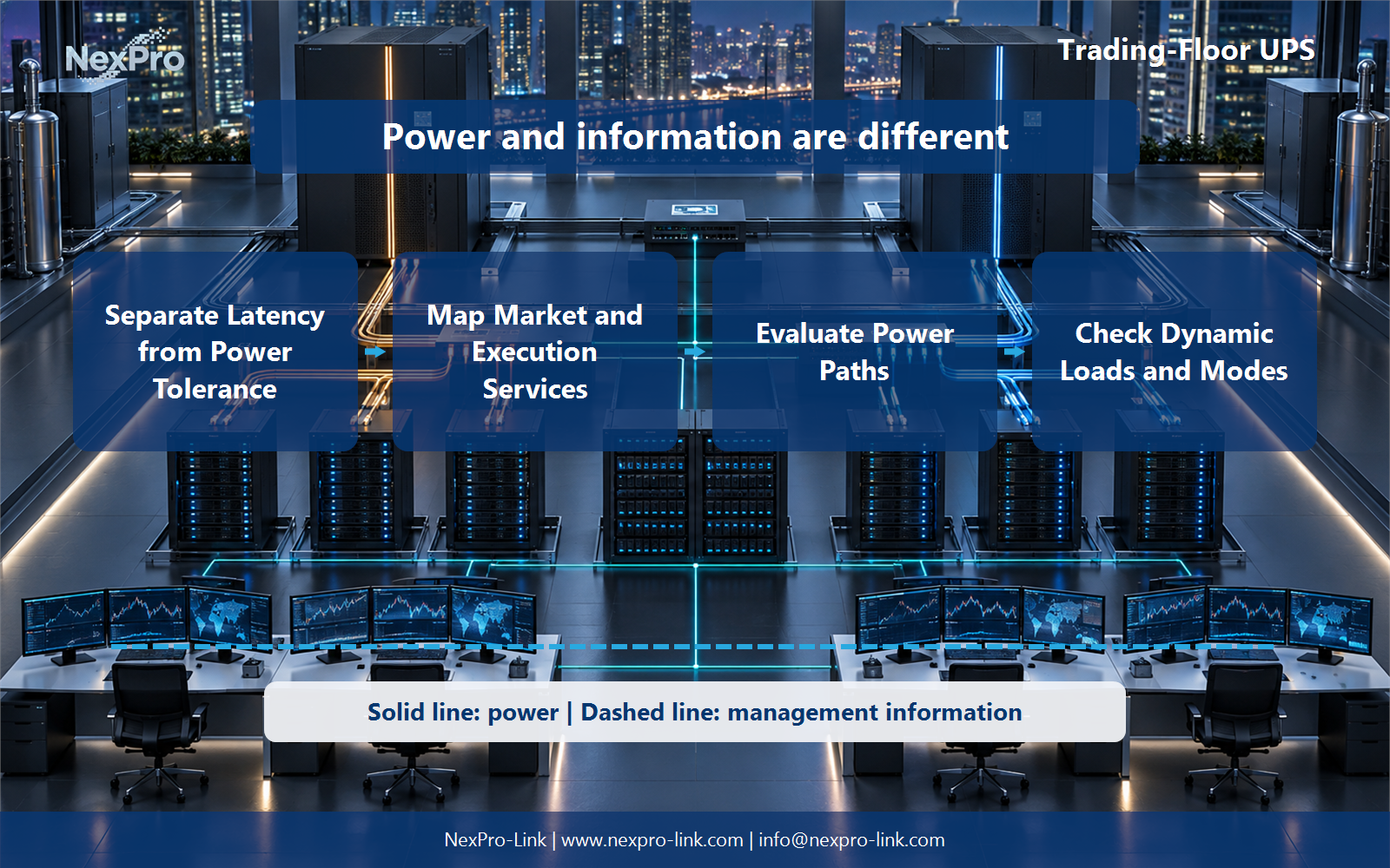
Draw power delivery as a solid path and management information as a separate dashed path. That distinction prevents an alarm or software command from being mistaken for an electrical protection function.
Section 04
Coordinate Recovery Governance
The application's operational and risk owners determine the restart and reconciliation process. UPS status can provide an input, but it should not independently release business activity. Document the dependency and authorization sequence without proposing unapproved production automation.
Assign the action, acknowledgement, timeout and escalation owner before commissioning. The useful battery interval is the time needed for this approved sequence plus reserve, not an arbitrary marketing duration.
Section 05
Frame a Technical Supply Request
Provide the approved power architecture and load requirements for equipment matching. NexPro-Link can discuss suitable supply options and documentation within that scope. Do not present a general UPS family as exchange-approved or guarantee trading outcomes without a specific project basis.
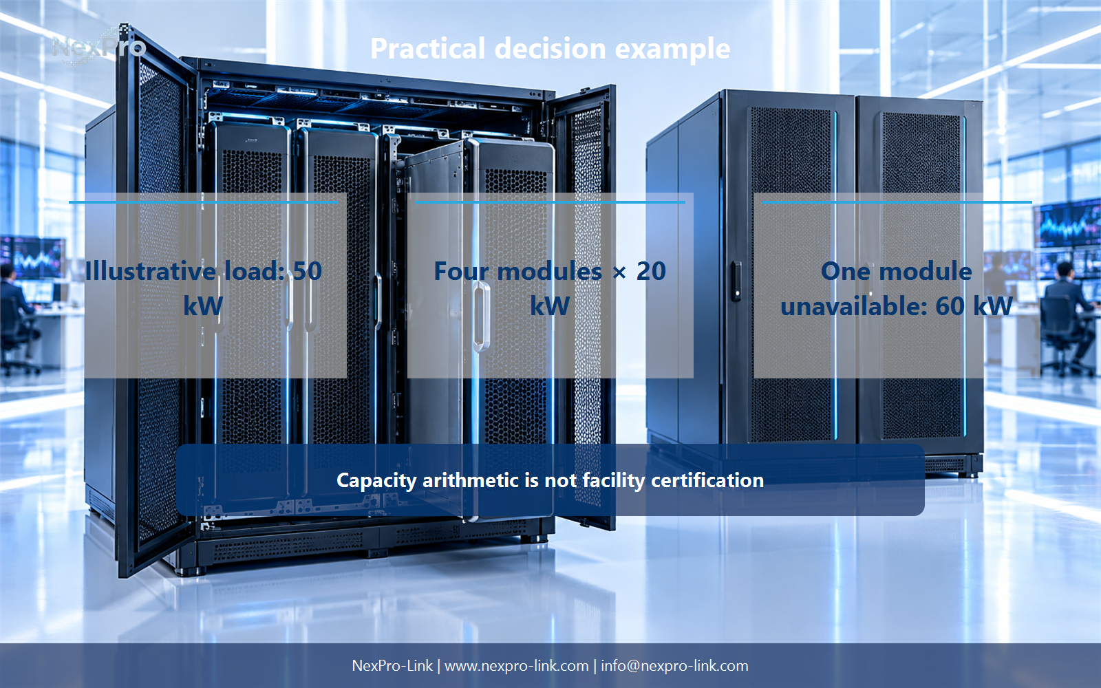
For the article's practical example, the stated teaching inputs are: Illustrative load: 50 kW. Four modules × 20 kW. One module unavailable: 60 kW. Capacity arithmetic is not facility certification. Treat these figures as planning assumptions, then replace them with measured or manufacturer-supported project data.
Engineering references
These sources support the general planning principles. Always use the selected product's current datasheet and applicable project standards for final design.