
Why do disk shelves get listed separately from controllers? They can have separate power feeds, different startup behavior and their own capacity requirements.
Section 01
Inventory the Complete Array
Why do disk shelves get listed separately from controllers? They can have separate power feeds, different startup behavior and their own capacity requirements. A plan built only around the controller chassis leaves out the shelves that hold the actual disk media, and often the switches that carry storage traffic. This guide works through a complete power boundary for a SAN or NAS array and its JBOD shelves, then turns that boundary into the inputs a supplier needs for a defined proposal.
They can have separate feeds, startup behavior and capacity requirements. Include controllers, expansion shelves and required storage networking in the load scope. A proposal based only on the controller chassis can omit the devices that hold the actual media.
The working question is simple: Why should disk shelves be listed separately from controllers? Record the answer as a service requirement before comparing UPS ratings or battery options.
| Decision area | Project question | Required output |
|---|---|---|
| Inventory the Complete Array | Why should disk shelves be listed separately from controllers? | Approved service objective |
| Trace A and B Connections | Do two power supplies always provide two independent routes? | Defined load and dependency boundary |
| Consider Full-Load Transfer | What load should one surviving power route support? | Reviewed power-path decision |

Section 02
Trace A and B Connections
No. Both may connect to the same distribution or UPS. Trace each route back to its source and mark shared components. The project objective determines whether independent paths are needed; a diagram should show the actual arrangement rather than count plugs.
Keep the load list, operating state and supporting dependencies in the same schedule. This makes omissions visible before runtime or capacity is discussed.
- Confirm the answer to: Do two power supplies always provide two independent routes?
- Separate measured demand, nameplate limits and committed growth.
- Identify the owner of each external service or approval.
Section 03
Consider Full-Load Transfer and Coordinate Cache and Shutdown
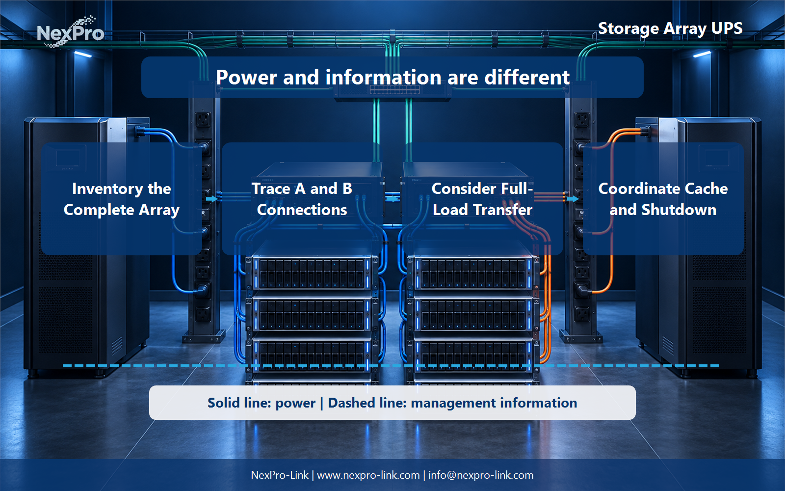
Use the equipment's supported failure-state behavior and the design objective. Load sharing in normal operation can change when one route is unavailable. Compare the surviving path's rating with that condition rather than assume normal half-load readings remain unchanged.
Follow the array's supported process for stopping host access, preserving data and powering down dependent components. Distinguish hardware cache protection from system runtime. For a project-specific decision, record hosts, I, O stop, controller, shelves and confirmation in the sequence. This keeps the equipment inputs and intended service outcome aligned.
Draw power delivery as a solid path and management information as a separate dashed path. That distinction prevents an alarm or software command from being mistaken for an electrical protection function.
Section 04
Keep the Fabric in the Plan
Yes. Hosts may lose access if the required network or storage switches stop. Include the fabric needed for operation or orderly shutdown, and document any independent paths. This keeps the protected service broader than the storage cabinet alone.
Assign the action, acknowledgement, timeout and escalation owner before commissioning. The useful battery interval is the time needed for this approved sequence plus reserve, not an arbitrary marketing duration.
Section 05
Prepare an Array-Level Power Schedule
Send the complete array and fabric schedule, failure-state demand, output interfaces and runtime objective. NexPro-Link can discuss UPS and rack-distribution equipment against that basis. Specialized array compatibility and final wiring remain governed by the equipment and project design.
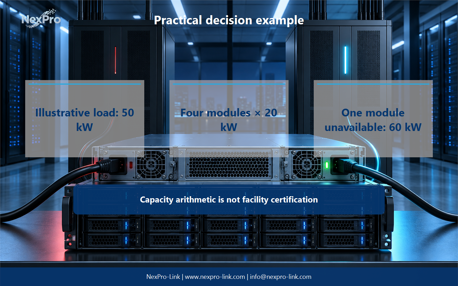
For the article's practical example, the stated teaching inputs are: Illustrative load: 50 kW. Four modules × 20 kW. One module unavailable: 60 kW. Capacity arithmetic is not facility certification. Treat these figures as planning assumptions, then replace them with measured or manufacturer-supported project data.
Engineering references
These sources support the general planning principles. Always use the selected product's current datasheet and applicable project standards for final design.