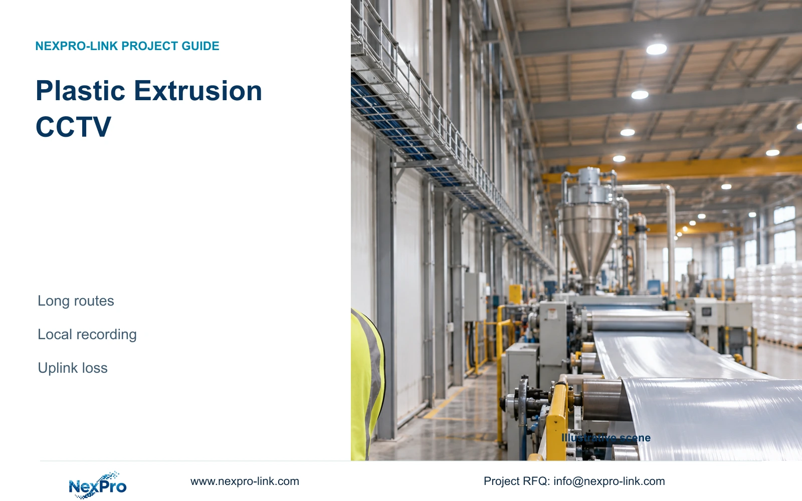
Compare routed cable lengths with nearby recording nodes for extrusion halls, keeping transfer detail, local power and uplink-loss behaviour in the same design.
Section 01
Separate long-line context from transfer detail
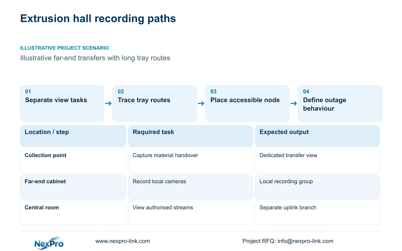
Plastic extrusion CCTV should use local access groups where actual cable routes justify them, with recording placed locally when footage must continue through uplink loss. Define overview and transfer-detail tasks before choosing cabinet positions. An overview can establish movement along an aisle; a collection or packing view should show the custody event at its own target plane. Neither task demonstrates extrusion quality or machine-protection performance.
Illustrative project scenario: The extrusion hall has long cable routes and limited access at the far production end. Assume finished material moves from a collection position toward packing and dispatch, with trays following service routes rather than straight lines. The engineer marks the collection point, accessible cabinet candidates and approved maintenance approaches. This gives the owner a decision between a nearby protected node and a longer network path, without assuming that every extended copper run can be treated as standard PoE.
Section 02
Locate cabinets using the installed route
Survey the intended tray path, vertical rises, cabinet entry and endpoint service allowance for each camera. Record these components against a link ID so the takeoff can be checked after machinery or trays move. Cabinet distance measured on a floor plan is only an initial estimate. Fluke guidance distinguishes a typical 90 m copper permanent link from a 100 m complete channel, so patch cords and the selected test configuration must remain identifiable.
A nearby cabinet is useful only if it has suitable operating conditions, a confirmed mains supply and service access. Keep ordinary switches, disks and batteries away from unsuitable heat, contamination or classified positions. Where the cabinet cannot be moved, compare an appropriate fibre path to an accessible powered node with any proposed copper-extension arrangement. For an extension, request the limits of every segment, the delivered device power and the complete supported configuration. Do not accept a headline distance as evidence that the camera will receive adequate power under its actual operating load.
Section 03
Specify what continues when the uplink is lost
For footage continuity during uplink loss, the camera-to-recorder path must remain within the functioning local network. A switch at the far end with a recorder only in the central room still depends on the uplink for recording. Draw the local cameras, access switch, recorder and disks as one recording group, then show authorised central viewing as a separate branch. State which equipment loses visibility and which should continue recording when that branch disconnects.
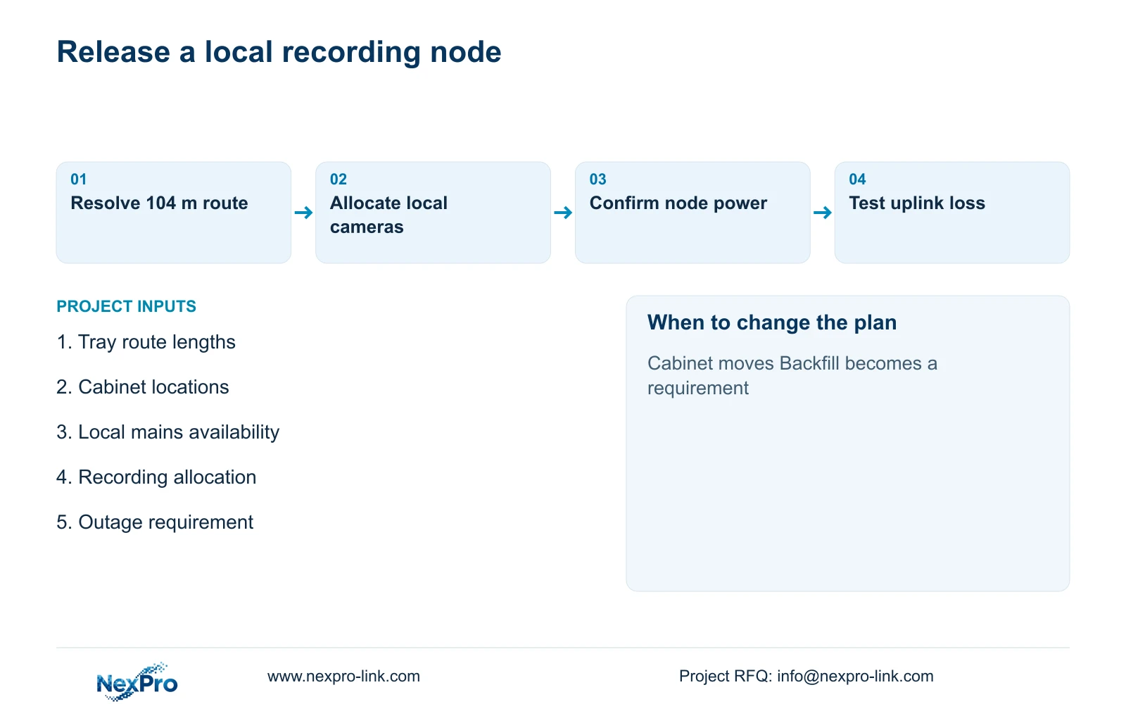
CASE01 uses one illustrative 32-camera node, so it cannot prove the capacity of a newly divided extrusion-hall design. Its useful lesson is to calculate each node independently. Allocate camera count, supported stream mode, average bitrate and retention to the actual local recorder, then check its own disk budget. During commissioning, arrange an approved uplink-disconnection test and confirm the local timeline, restored viewing and export. Local recording does not establish automatic central backfill, recorder failover or recovery from a local disk or power failure.
Section 04
Redesign the overlength link before ordering cable
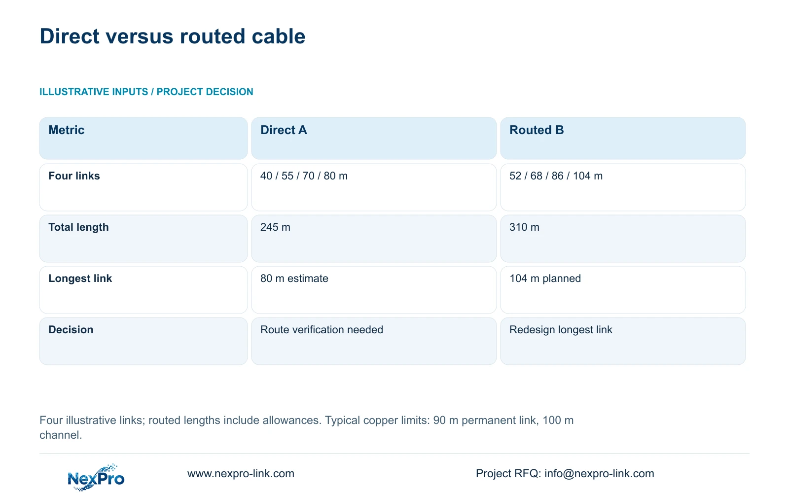
The supplied illustrative takeoff compares four straight-line estimates of 40, 55, 70 and 80 m with routed permanent-link lengths of 52, 68, 86 and 104 m, including installation allowances. Use total_m = sum(individual_link_lengths), then check each link separately. Option A totals 245 m; Option B totals 310 m. The longest estimate changes from 80 m to a planned 104 m permanent link.
The extra 65 m affects quantity, but the 104 m link determines the architecture decision. It cannot simply be approved as a typical 90 m permanent link, nor treated as a 100 m complete channel by ignoring its definition. Relocate the cabinet or specify an appropriate alternative path, then recalculate the affected route. Dividing 310 m by reel length before resolving that link would produce a purchasing quantity for an unresolved design. The straight-line option also remains unverified even though every estimate is below 90 m.
| Metric | Option A: direct estimates | Option B: routed takeoff |
|---|---|---|
| Individual lengths | 40 / 55 / 70 / 80 m | 52 / 68 / 86 / 104 m |
| Total cable | 245 m | 310 m |
| Longest permanent link | 80 m estimate | 104 m planned |
| Design status | Actual routes unverified | One link needs redesign |
Section 05
Compare node costs with complete dependencies
Prefer a nearby protected recording node when it resolves the overlength route and the owner requires footage during backbone interruption. Retain central recording when compliant routes are available and its failure behaviour meets the operating brief. A local node adds cabinet space, storage administration, electrical work and maintenance visits. A fibre backbone adds its own optics, terminations and testing. Compare these complete scopes rather than assuming either architecture is cheaper.
The NexPro-NVR4449-4K is a recorder reference with 320 Mbps input and four SATA bays, each listed up to 18 TB. Its suitability depends on the allocated stream modes and operating workload, not merely available channels. NexPro-Link's SP5648 Cat6 patch panel and DT968MX module can support an appropriate termination schedule; neither is a bulk-cable specification. Obtain actual camera demand and complete switch AC input for local power sizing. A central UPS does not protect a remote cabinet whose mains supply lies outside its powered circuits.
Section 06
Release the route and outage requirements together
Issue a security handover map that links each transfer view to its cabinet, recorder and power source. The equipment schedule should distinguish supplied local recording hardware, retained backbone facilities and electrical or mounting work provided by the installer. Any specialist position needs its own environmental and interface requirements. This prevents a route revision from quietly moving a camera onto an unprotected or unsuitable node.
NexPro-Link can discuss model matching and coordinated BOQ support from this node-based schedule. Require cable test records for the selected link type, configuration records for each recorder and an outage demonstration tied to the approved drawing. Operators also need a way to identify the correct local recording group when central viewing is unavailable. A normal retrieval display may be sufficient; a display wall is a separate operator requirement. Before shipment, freeze cabinet IDs and location labels so the packing plan still matches the revised cable routes.
Section 07
Buyer questions
Does fibre solve both distance and camera power? It can provide the appropriate data path, but the remote cameras and node still need a separately designed local power supply. Include that supply and its backup objective in the quotation.
Can central staff recover recordings after an uplink outage? Require a demonstrated retrieval workflow for the chosen recorder and client. Accessible local footage does not establish automatic synchronization into a central archive.
Is a PoE extender acceptable instead of another cabinet? It may be, if the exact arrangement meets every segment's data and power requirements and can be maintained. Compare the verified configuration with the complete local-node scope.
Section 08
Resolve the far-end recording node
Email your routed camera-link takeoff, candidate cabinet and mains locations, transfer-view schedule, and required uplink-loss behaviour to info@nexpro-link.com for a node-based equipment discussion.
Engineering references
These sources support the general planning principles. Always use the selected product's current datasheet and applicable project standards for final design.