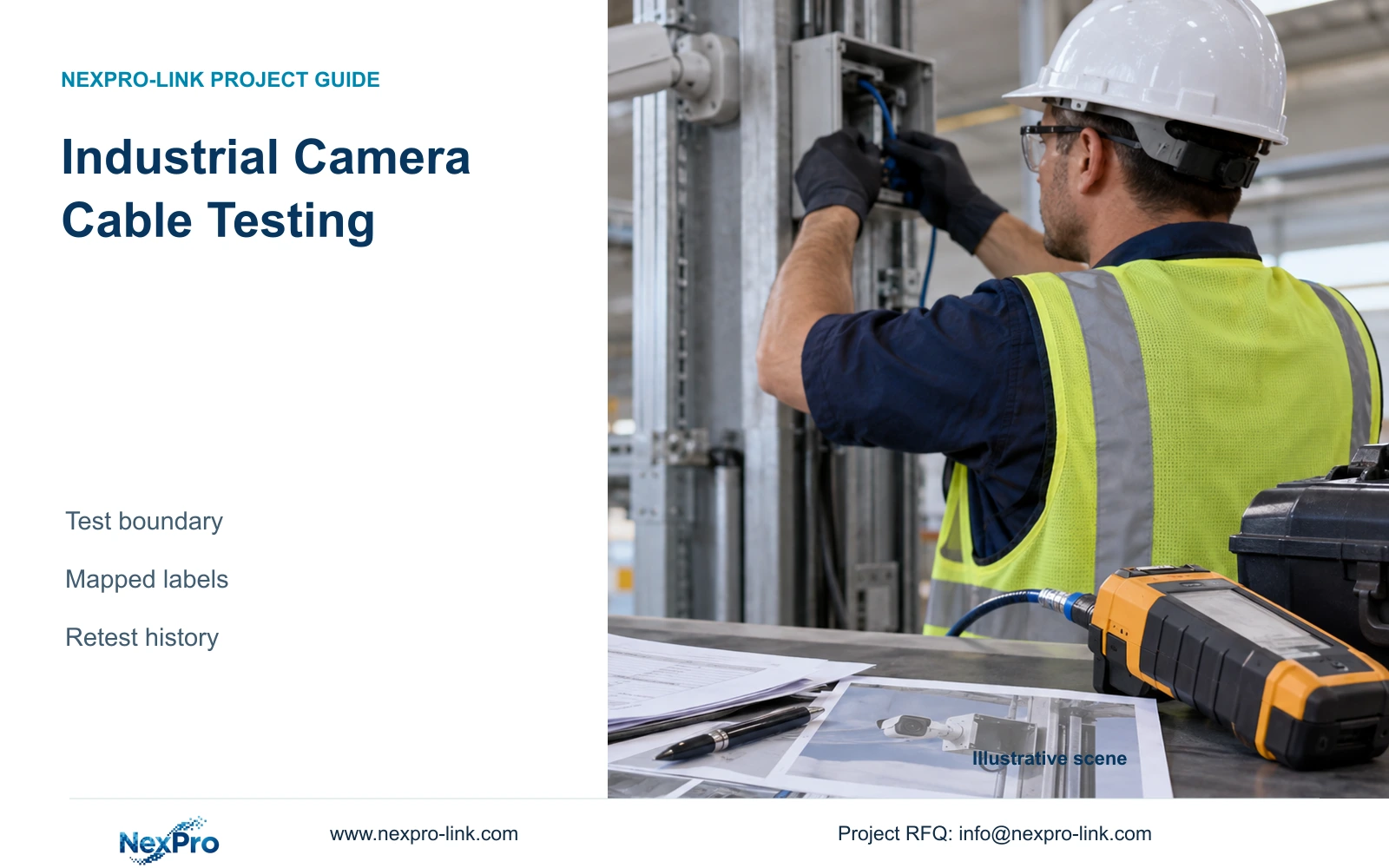
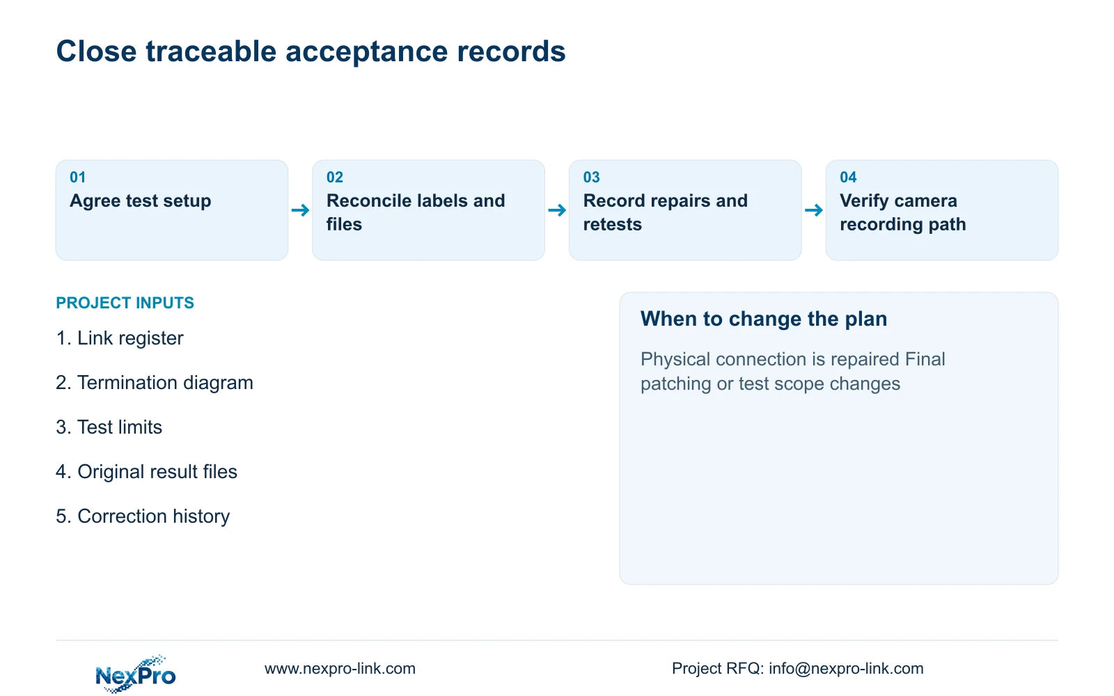
For a disputed label, trace the tester file to the physical endpoints and contemporaneous installation record before correction. Preserve the original result and the reason for relabeling.
Section 01
Match the test configuration to the installed connection
For a disputed label, trace the tester file to the physical endpoints and contemporaneous installation record before correction. Preserve the original result and the reason for relabeling. If identity cannot be established, retest the actual link under the approved setup; editing the report name cannot manufacture missing acceptance evidence.
Industrial camera cable testing should use the applicable connection boundary, test configuration and link identity. A permanent-link result and a complete-channel result describe different scopes. Accept reports only when the recorded setup matches the approved installation, and keep any corrections and replacement tests traceable to the same physical link.
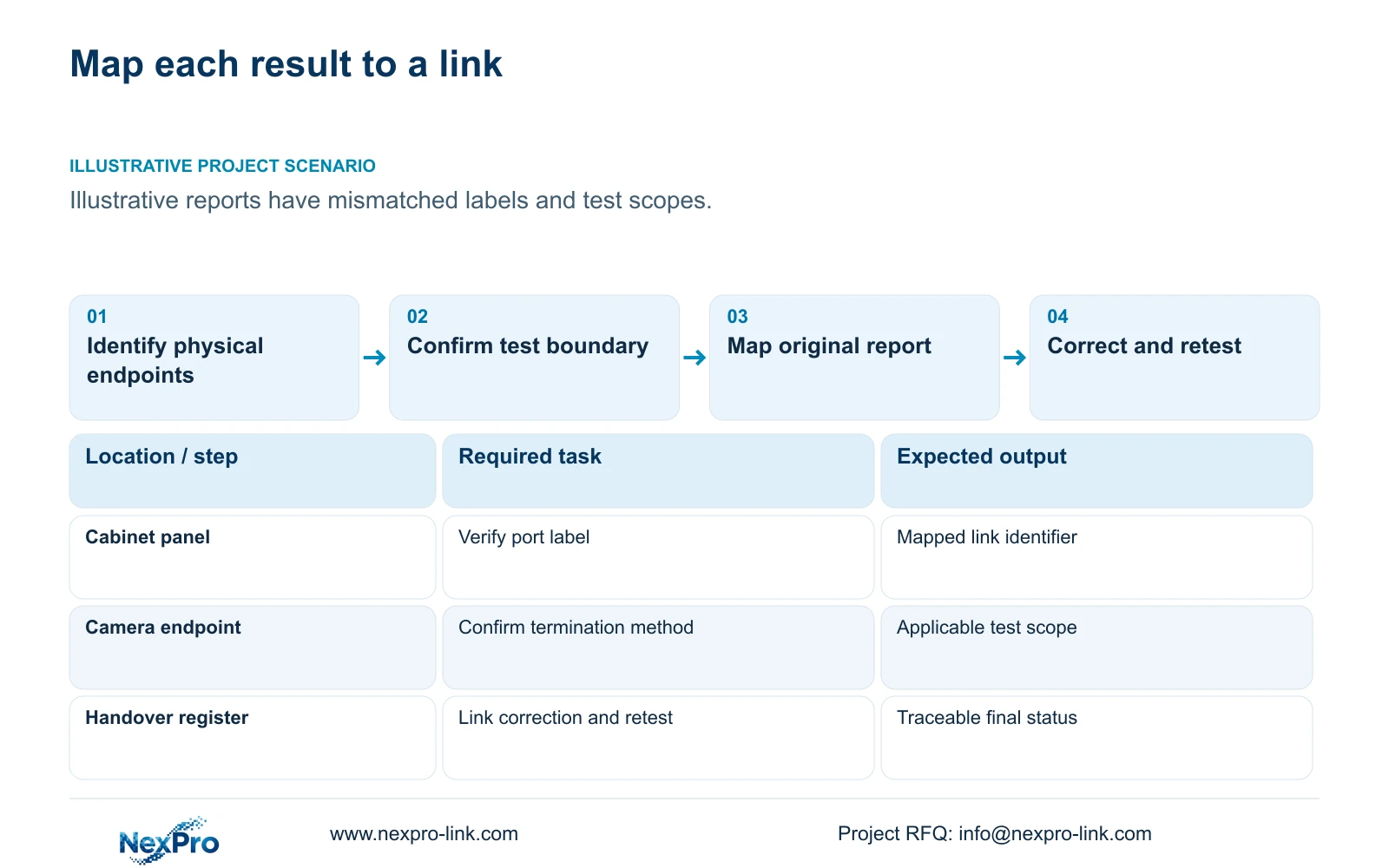
Illustrative project scenario: The contractor has test reports, but the identifiers and test setup do not match the as-built links. Assume a 32-camera factory handover follows CASE01's module-ended planning arrangement, while part of the report package uses labels that the owner cannot map to camera locations. No supplied report establishes that those installed links have passed.
Start by confirming the approved termination method. A module-ended fixed link, a channel including patch cords and a direct camera-plug arrangement need the corresponding test scope and suitable setup. Ask the installer to identify what was physically connected during each test. A tester brand name or a green summary icon cannot resolve an undocumented boundary.
Section 02
Build one mapping from camera location to report
Create a link register containing camera location, cabinet, panel port, endpoint label and test-record identifier. Include the installation drawing revision and any accepted label translation. The installer should verify the physical endpoints against that register before the engineer reviews results, so a report for one run cannot be accepted for a different camera.
CASE01 provides useful illustrative identifiers such as N1-CAM01 through N1-CAM32. Its continuous lengths run from 41 to 76 m and total 1,872 m. These planned lengths are a reconciliation reference, not measured pass records. Investigate an unexplained difference between the scheduled route and the reported length rather than editing the schedule to make the documents appear consistent.
Keep the original machine-readable test files where available, along with the reviewable export. Record the test scope, selected limit, date and relevant instrument details in the handover schedule. If old labels are retained through a documented mapping, make that mapping available to the owner rather than requiring maintenance staff to search through contractor emails.
Section 03
Separate documentation correction from physical repair
Classify a mismatch before deciding what to repeat. A proven label translation may require a corrected register and report reference. An uncertain physical identity requires endpoint verification. A test performed under the wrong connection boundary needs the appropriate new test. A failed installed result requires investigation and any necessary repair before retesting.
For physical work, record the affected link, observed problem, action taken and replacement result. Preserve the earlier result as superseded rather than deleting the history. If a module is changed or a route is shortened, update the component or as-built record at the same time. The engineer should be able to follow why the final accepted result differs from the first submission.
Assign repair and retest responsibility before procurement or installation starts. Identify how disputed components and damaged cable will be handled, without treating every failure as proof of a supplier defect. The commercial record should distinguish supplied materials, installation workmanship and owner-requested changes. This prevents an unresolved acceptance issue from becoming an unsupported warranty claim.
Section 04
Use route arithmetic to identify review exceptions
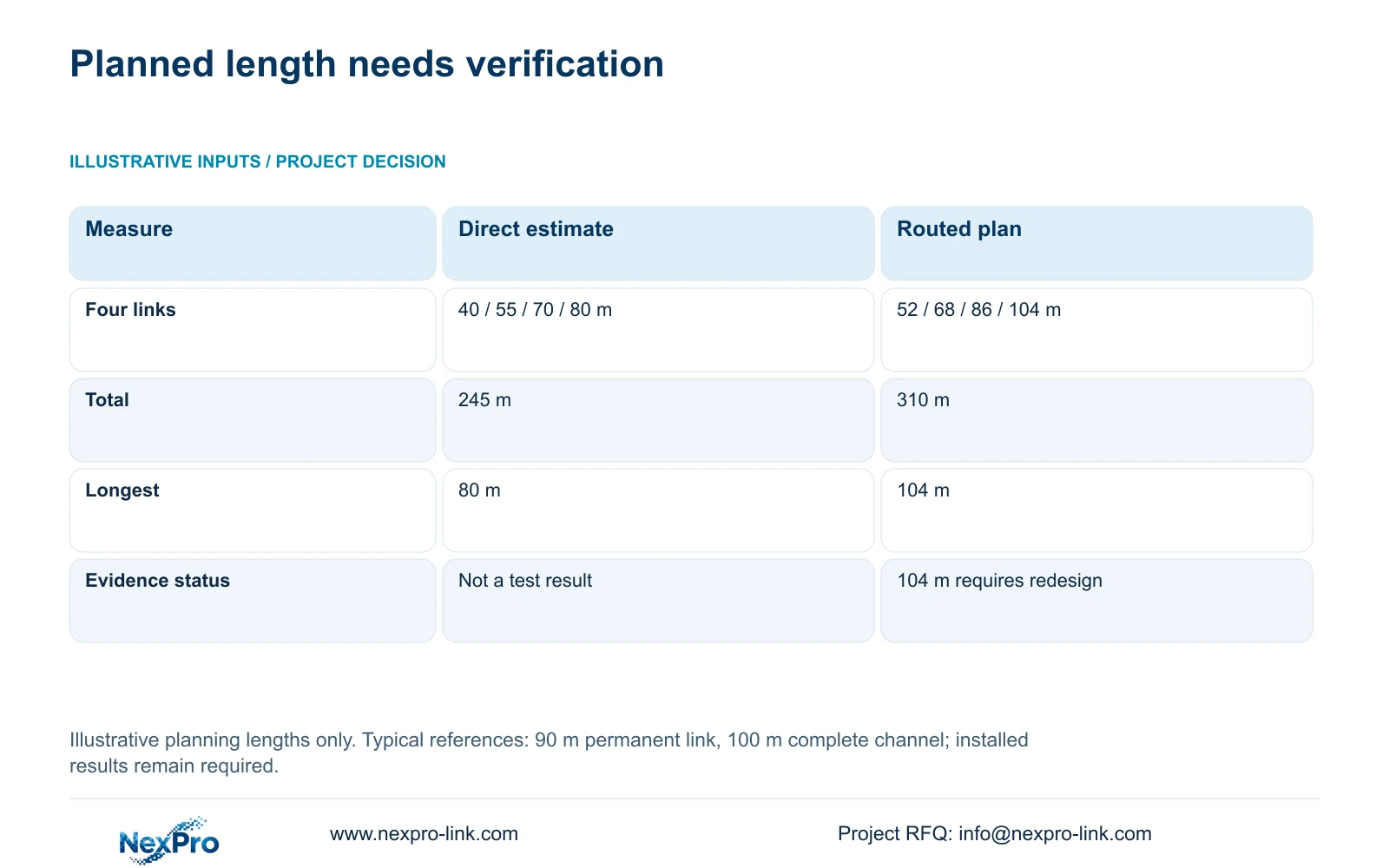
The four-link illustration uses direct estimates of 40, 55, 70 and 80 m, compared with routed lengths of 52, 68, 86 and 104 m including installation allowances. total_m = sum(individual_link_lengths) gives 245 m and 310 m. These are planning figures; they cannot be entered into the handover register as measured test results.
Fluke Networks guidance gives the typical distinction between a 90 m permanent link and a 100 m complete channel. The planned 104 m permanent link needs redesign under that stated boundary. Selecting a different report heading cannot approve it. Resolve the route or architecture, then test the resulting physical installation using the applicable setup.
The decisive difference between testing scopes is the connection being evaluated. If patch cords are added after permanent-link acceptance, identify their role in the final operational channel. If the owner requires complete-channel acceptance, test the specified channel and control the installed patching arrangement. The table connects each scope with the evidence the engineer should request.
| Installation scope | Record to request | Acceptance consequence |
|---|---|---|
| Module-ended permanent link | Applicable fixed-link setup and mapped ID | Does not by itself accept later patch cords |
| Complete channel | Applicable setup including specified cords | Record the final channel arrangement |
| Direct camera-plug arrangement | Applicable method for actual termination | Do not relabel as a different boundary |
| 104 m planned permanent link | Approved redesign, then installed test | Hold acceptance under stated 90 m reference |
Section 05
Verify the installed camera workflow after cabling review
Once the required cabling records are reconciled, check the actual camera workflow: the camera powers through its intended supply, reaches the assigned network path and records to the intended recorder. Use an agreed commissioning sequence and record any interruptions. A cable report and an operational recording check answer related but different acceptance questions.
For CASE01, the assumed recording payload is 128 Mbps from 32 cameras at 4 Mbps each. That total is a planning input and does not prove the performance of a particular installed switch, uplink or recorder configuration. Keep device setup and network verification separate from the category test result so faults can be investigated at the correct boundary.
Recommend full reconciliation of the agreed link schedule before final handover. Where staged opening is necessary, identify accepted links and outstanding links by ID, with a responsible party and closure condition. Avoid declaring the entire installation passed when only a selected package of reports has been reviewed or when final patching remains undocumented.
Section 06
Procure a handover record that remains usable
The tender should state the required test boundary, labels, report format and correction history. Include the link register and accepted termination schedule so bidders price the same deliverable. Testing and retesting should be named work items, with access arrangements for completed production areas recorded before the crew needs to return.
NexPro-Link's SP5648 Cat6 48-port panel and DT968MX Cat6 tool-less module are identifiable termination references. Their product descriptions do not certify every installed channel. Match supplied components to the approved link method and preserve exact identities in the submittal. A component replacement should trigger review of the affected installed connection rather than an assumption that its category label is sufficient.
NexPro-Link's BOQ support can coordinate relevant component documentation and technical deviations. The local installer supplies and reconciles installed test evidence, and the buyer's project team approves acceptance. Deliver the final register, as-built connections and superseded-result history together so maintenance staff can locate the correct camera link and understand any earlier corrective work.
Section 07
Buyer questions
Can a label mismatch be fixed without retesting? Sometimes, if physical identity and the original test scope are proven and an accepted mapping preserves traceability. If either remains uncertain, verify the endpoints and perform the necessary new test.
Are camera live images enough for cabling acceptance? They demonstrate an operational observation at that time. They do not replace the agreed installed cabling test records or establish the required category result.
Should failed results remain in the handover file? Keep them in the correction history, clearly marked superseded and linked to the repair and final accepted result. Present the final status separately so the owner can use the package without ambiguity.
Section 08
Define the testing handover scope
Send your link register, termination diagram, required test boundary and a representative mismatched report to info@nexpro-link.com to discuss component documentation and the associated project scope.
Engineering references
These sources support the general planning principles. Always use the selected product's current datasheet and applicable project standards for final design.