Plan factory perimeter CCTV design with practical guidance on segment the boundary by risk and geometry and build remote network and poe zones. NexPro-Link project guide.
Section 01
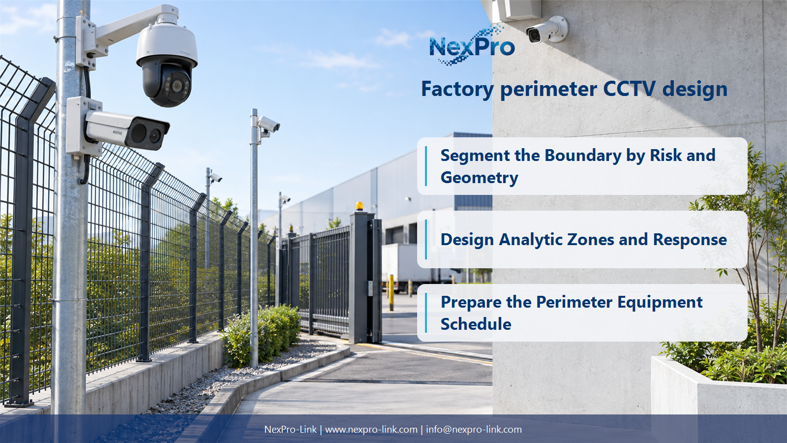
Segment the Boundary by Risk and Geometry
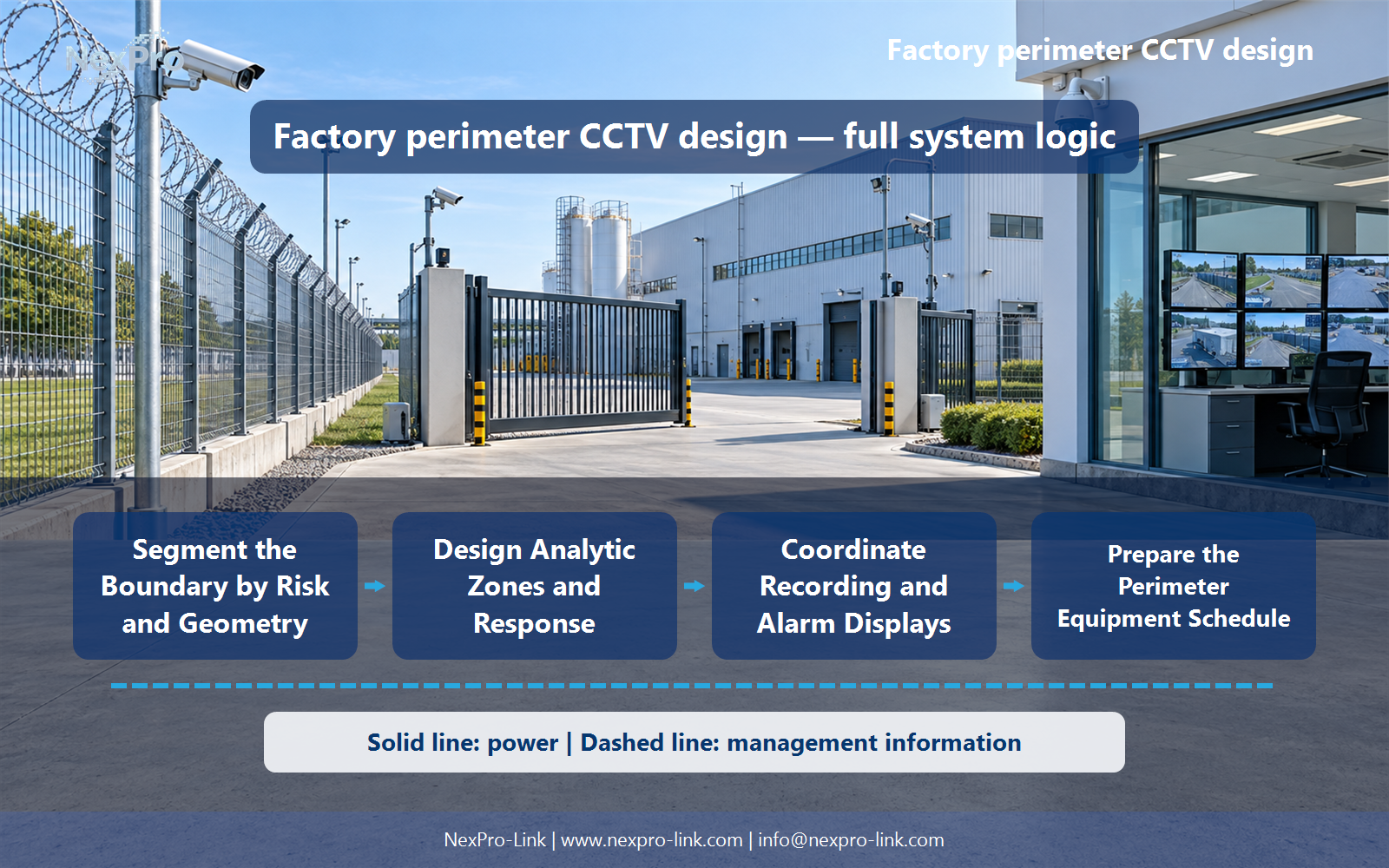
Divide the boundary into visible segments, entrances and obstructed areas, then define detection and verification tasks. Fence length alone cannot determine camera count. Corners, elevation, vegetation and lighting can create separate views even when a nominal illumination range appears sufficient.
Turn the answer into a working record using Segment, Geometry, Obstruction, Task, Coverage.
| Decision area | Buyer question | Required output |
|---|---|---|
| Segment the Boundary by Risk and Geometry | How should perimeter camera quantity be estimated? | Divide the boundary into visible segments, entrances and obstructed areas, then define detection and verification tasks. |
| Separate Detection and Identification | Is thermal imagery sufficient to identify an intruder? | Thermal can support target detection in suitable conditions, but detailed visual identification often needs a complementary visible-light view. |
| Design Analytic Zones and Response | What should an intrusion rule specify? | Define the boundary, target direction, schedule and operator response, including how nuisance activity is handled. |
Section 02
Separate Detection and Identification
Thermal can support target detection in suitable conditions, but detailed visual identification often needs a complementary visible-light view. Define the required action after detection. Neither thermal nor infrared should be presented as seeing through all obstructions or guaranteeing recognition at its longest advertised range.
Use Task, Thermal role, Visible-light role, Required detail to compare options on the same basis. Keep product capability, project assumption and operating responsibility in separate columns.
Section 03
Design Analytic Zones and Response
Define the boundary, target direction, schedule and operator response, including how nuisance activity is handled. Detection capability may reside in a camera or recording platform. Match the rule and event interface to the chosen devices rather than assuming any AI-labelled NVR supplies every analytic function.
The project output should make Rule, Direction, Schedule, Event source, Response traceable from input to acceptance.
- Confirm the answer to: What should an intrusion rule specify?
- Record the project fields: Rule / Direction / Schedule / Event source / Response.
- Keep product capability, project assumptions and site responsibility in separate records.
Section 04
Build Remote Network and PoE Zones
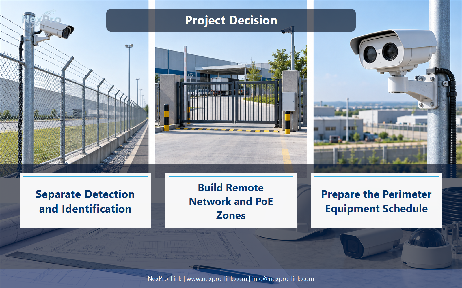
Use supported local camera links and appropriate backbone segments based on distance, power and maintenance access. Calculate each field switch's PoE demand independently. Unpowered fiber endpoints or excessive unmanaged cascades can interrupt the whole response path even when the cameras themselves suit the task.
Record Field cabinet, Cameras, PoE, Fiber link, Local supply before selecting a product family. That makes later substitutions possible without silently changing the operational requirement.
Section 05
Coordinate Recording and Alarm Displays
Only when the event and display-management functions are supported and configured together. Define which view opens, how operators acknowledge it and where related recordings are retrieved. Keep recording continuity independent of a failed wall or operator workstation where the architecture allows it.
Review Event, Display action, Recording reference, Operator with the party that will operate or maintain the system.
Section 06
Prepare the Perimeter Equipment Schedule
Include field switches, local power and backup, enclosures, mounts, data routes, recording capacity and operator display functions. Identify specialist thermal equipment separately from standard varifocal camera examples. The BOQ should connect each boundary segment to a usable response and maintenance arrangement.
Use Boundary segment, Equipment, Route, Backup, Supply owner as the handoff between design and procurement.
Engineering references
These sources support the general planning principles. Always use the selected product's current datasheet and applicable project standards for final design.