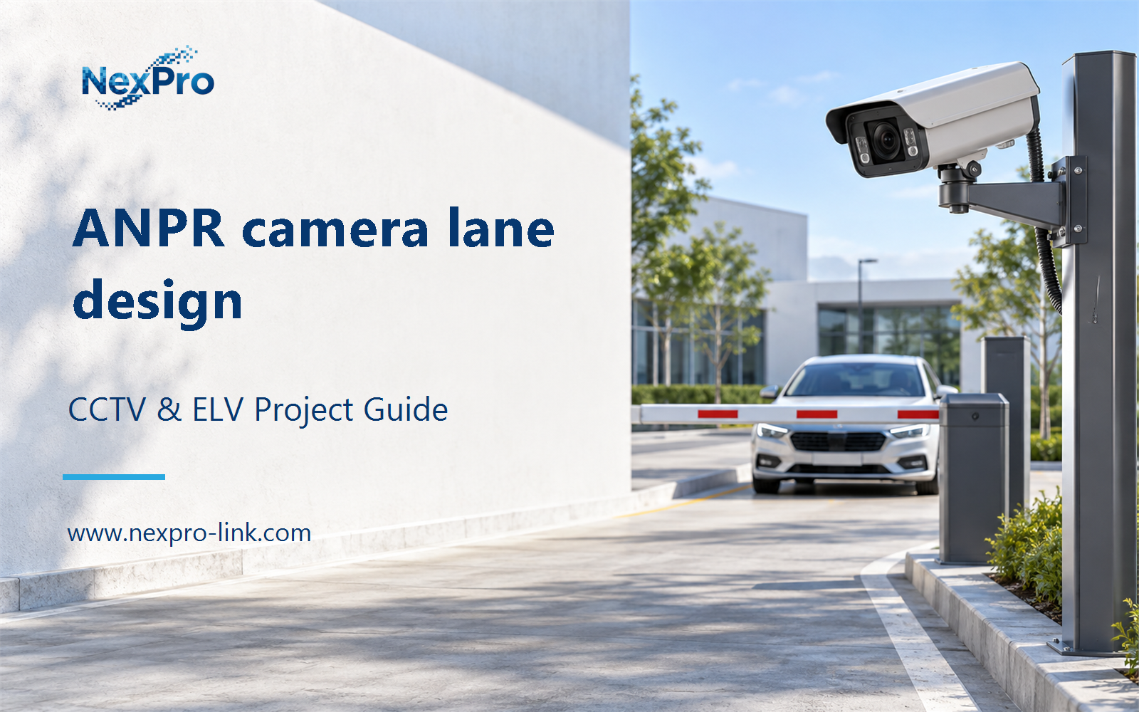
Plan ANPR camera lane design with practical guidance on define plate capture and recognition objectives and balance shutter and illumination. NexPro-Link project guide.
Section 01
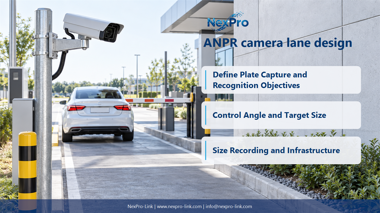
Define Plate Capture and Recognition Objectives
Capture concerns obtaining a usable plate image; recognition concerns interpreting its characters through the selected processing system. Specify both outcomes and their conditions. A successful vehicle detection or a zoomed overview does not prove readable plate capture or accurate character recognition.
Turn the answer into a working record using Objective, Input, Output, Test condition, Denominator.
| Decision area | Buyer question | Required output |
|---|---|---|
| Define Plate Capture and Recognition Objectives | What is the difference between plate capture and recognition? | Capture concerns obtaining a usable plate image; recognition concerns interpreting its characters through the selected processing system. |
| Set the Capture Zone and Lane Geometry | How should lane width influence camera placement? | Use the actual vehicle path, plate position and target area at the capture distance to determine framing. |
| Control Angle and Target Size | Why do mounting angle and plate size matter? | They affect the visible character detail and distortion presented to the recognition system. |
Section 02
Set the Capture Zone and Lane Geometry
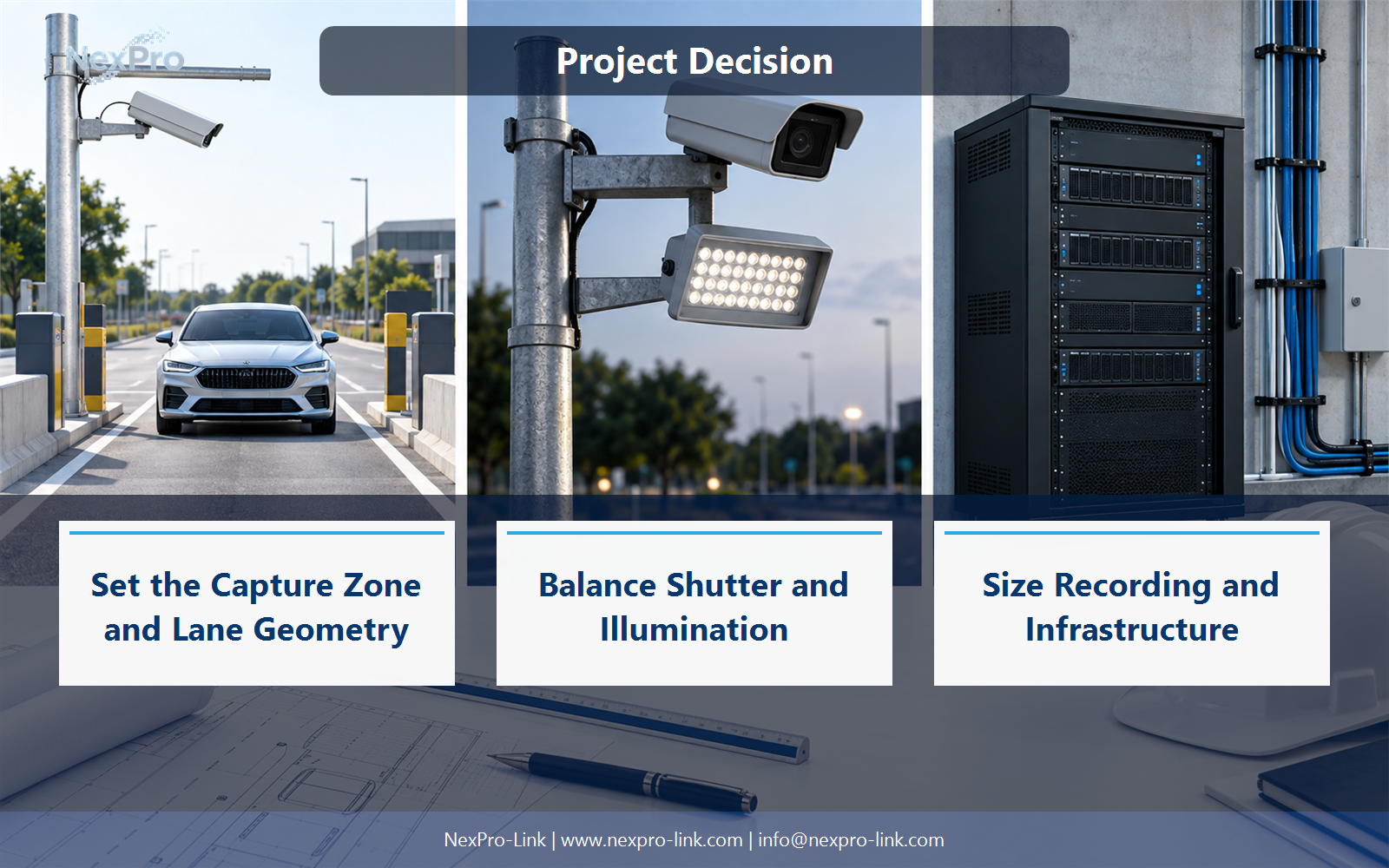
Use the actual vehicle path, plate position and target area at the capture distance to determine framing. Include stopping variation and multiple-lane risk. A nominal lane width does not by itself determine one universally correct focal length or mounting height.
Use Lane, Capture distance, Target width, Framing, Variation to compare options on the same basis. Keep product capability, project assumption and operating responsibility in separate columns.
Section 03
Control Angle and Target Size
They affect the visible character detail and distortion presented to the recognition system. Select the geometry within the intended platform's supported conditions. Do not reuse general overview mounting simply because it sees the lane; a plate task may need a dedicated view.
The project output should make Camera height, Horizontal angle, Vertical angle, Plate pixels traceable from input to acceptance.
- Confirm the answer to: Why do mounting angle and plate size matter?
- Record the project fields: Camera height / Horizontal angle / Vertical angle / Plate pixels.
- Keep product capability, project assumptions and site responsibility in separate records.
Section 04
Balance Shutter and Illumination
No. Motion, exposure time, plate reflectivity and the illuminator arrangement affect the captured characters. Strong illumination can also produce glare or saturation. Use representative plates and operating speeds to select the capture settings instead of equating maximum IR reach with recognition range.
Record Speed, Exposure, Illumination, Glare, Plate image before selecting a product family. That makes later substitutions possible without silently changing the operational requirement.
Section 05
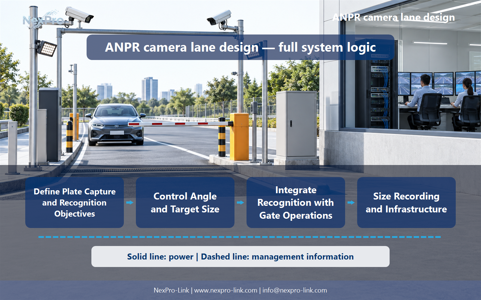
Integrate Recognition with Gate Operations
Define the recognized event, permission decision, command interface and exception handling. Gate safety remains a separate function of the appropriate system. Avoid assuming that a relay output or a recognized plate is sufficient to authorize every movement or resolve ambiguous reads.
Review Event, Access decision, Interface, Gate action, Exception with the party that will operate or maintain the system.
Section 06
Size Recording and Infrastructure
Include capture and context cameras, supported recognition processing, recording, storage, operator access and the complete power and network path. Specify outdoor routes and illumination loads. A sample 90-day retention period is a project assumption, not a universal rule or a supplied-model guarantee.
Use Lane, Capture, Processing, Storage, Display, Power, Cable as the handoff between design and procurement.
Engineering references
These sources support the general planning principles. Always use the selected product's current datasheet and applicable project standards for final design.