Plan around the defined workload and maintenance states. A brand name does not by itself prove data confidentiality or cloud availability.
Section 01
Define the Infrastructure Boundary
Plan around the defined workload and maintenance states. A brand name does not by itself prove data confidentiality or cloud availability.
The first question is which infrastructure the UPS plan should include. Start with the approved site scope. List the compute, storage, network and management equipment that must stay up. Then record the external and shared services the room depends on, because those sit outside the UPS yet still shape what it must do.
A scope map keeps the inputs honest. For a two-phase government cloud room it could look like this:
The PoE line matters. If a switch's input already includes its powered endpoints, do not add those endpoints again. Double counting inflates the load and then the UPS rating.
The map aligns the equipment inputs with the service the room must deliver. The UPS protects what the map says is in scope.
| Decision area | Project question | Required output |
|---|---|---|
| Define the Infrastructure Boundary | Which infrastructure should the UPS plan include? | Scope map: compute / storage / network / management / external |
| Separate Logical and Electrical Redundancy | Does clustered software prove independent power? | Path matrix: node group / feed / shared point / failure state |
| Plan Incremental Capacity | How should future demand be included? | Phase table: demand / retained capacity / distribution / space |
Section 02
Separate Logical and Electrical Redundancy
Clustered software does not prove independent power. Node groups can share a source, a distribution board, a cooling loop or a room service. More hosts is a compute resilience measure, and it says little about the electrical path behind those hosts.
A path matrix shows where the groups meet.
The last column carries the decision. The architecture should show which workload support remains after a failure. Counting hosts does not establish power resilience, because all of those hosts may hang off one path.
Section 03
Plan Incremental Capacity
Future demand splits into two parts. Committed installation phases are known. Uncertain growth is not. Mixing them inflates the UPS, and treating them as one number hides the states the room must operate in.
Keep the two apart and compare usable capacity. A phase table helps.
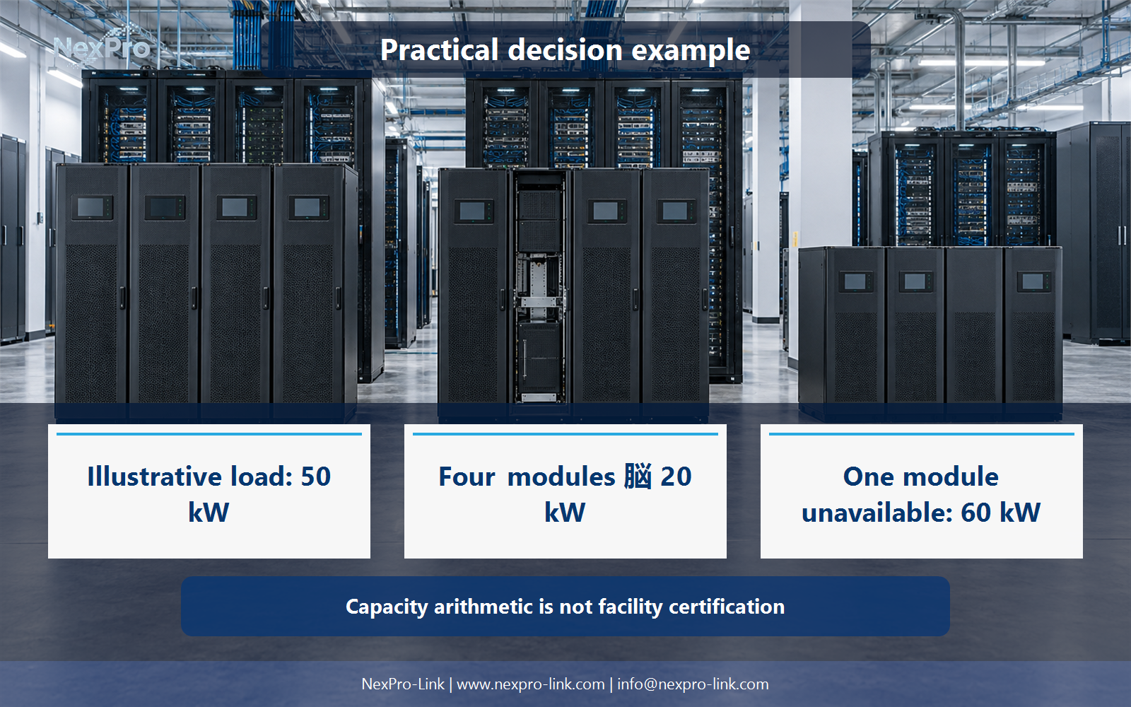
The example assumes four 20 kW modules, giving 80 kW normal and 60 kW with one module out. Phase 2 adds racks but no modules, so the retained rating stays 60 kW. That may still work, but only if the distribution, space and source accept the added racks. Modularity makes growth easier to discuss. It does not remove those other checks.
- Confirm the answer to: How should future demand be included?
- Draw electrical power as a solid path and management information as a separate dashed path.
- Keep external services and specialist approvals outside the UPS equipment claim.
Section 04
Budget the Source and Recharge
When utility power returns, the source does more than carry live IT load. It carries battery recharge and auxiliary loads at the same time. Recharge depends on the selected charger and battery configuration.
A source budget separates the loads so none is forgotten.
If the source is approved for 80 kW continuous, 70 kW fits. If it is approved for 60 kW, it does not. A nominal UPS and generator rating that match on paper does not by itself prove adequate recovery performance.
Section 05
Define Maintenance Outcomes
A maintenance objective should name the component or path that can be unavailable, and the service that must stay up. A label like N+1 does not demonstrate the whole facility's maintenance capability. A product certificate does not either.
The condition column forces the team to check batteries, distribution and cooling. That check is the one many plans skip.
Section 06
Prepare a Cloud-Power RFQ
At this point the team can turn the decisions into a request for quote. NexPro-Link receives the authorized rack schedule, growth phases, power paths and applicable procurement requirements. From there NexPro-Link can discuss equipment configurations within that scope.
The RFQ stays inside the actual specification. It does not need invented localization, security or facility-certification claims.
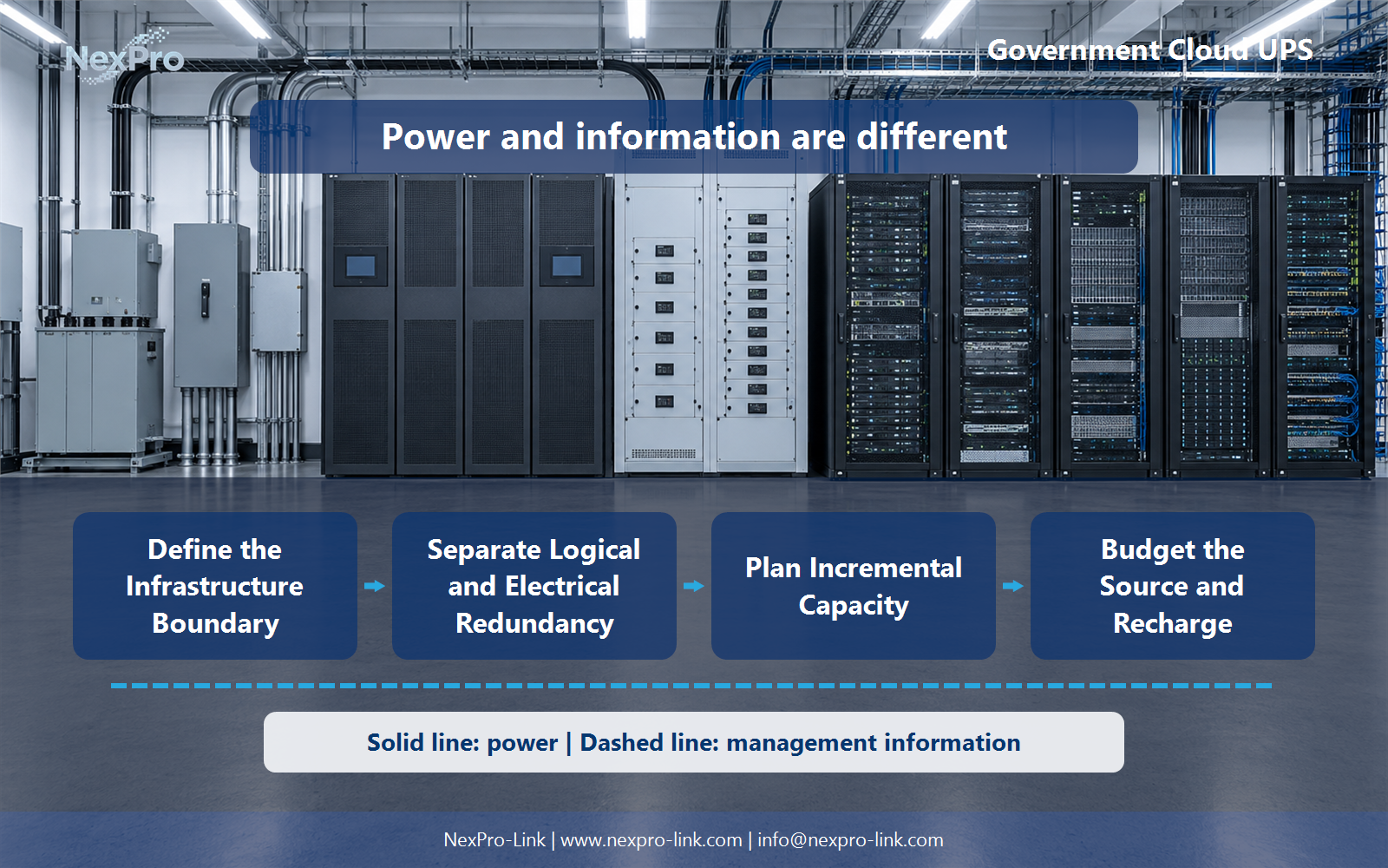
[Figure 02: mechanism and dependency diagram. Caption: The functional relationships behind government cloud UPS infrastructure scope; power delivery and management information are shown separately.]
Engineering references
These sources support the general planning principles. Always use the selected product's current datasheet and applicable project standards for final design.