For each converter-reuse candidate, record the accepted stream/power trial and the practical recabling fallback. Check fallback access, node space and reconnection sequence before the restricted window.
Section 01
Approve reuse by the complete transmission and power path
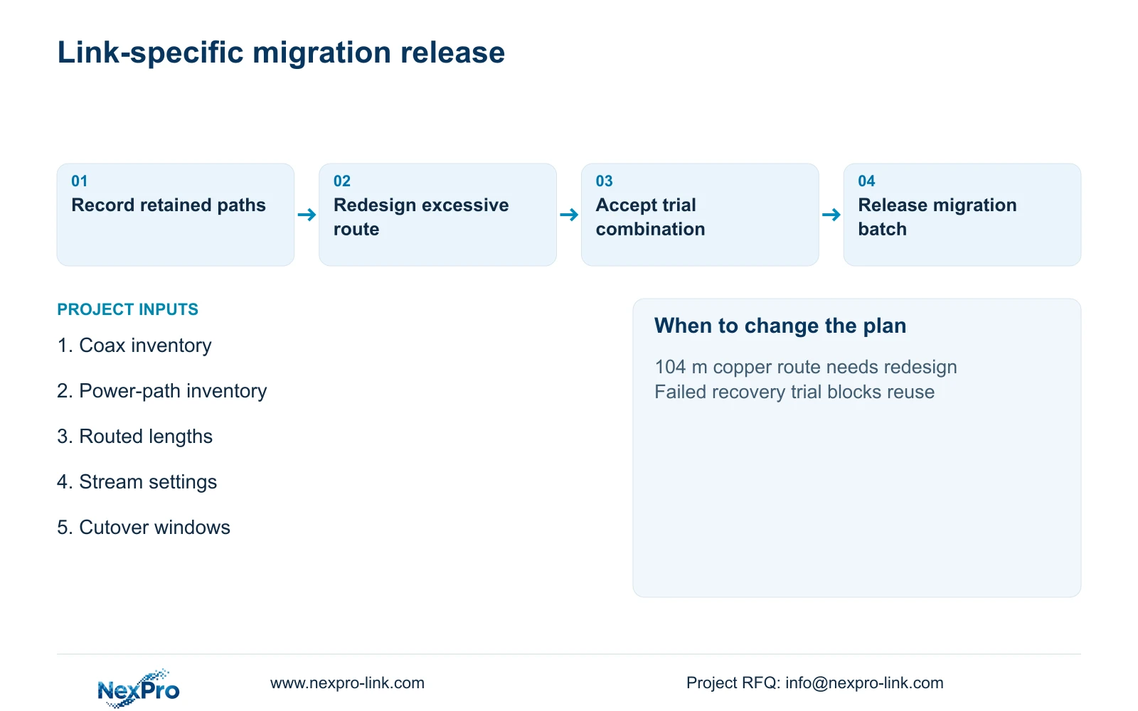
For each converter-reuse candidate, record the accepted stream/power trial and the practical recabling fallback. Check fallback access, node space and reconnection sequence before the restricted window. If the trial fails, use the approved alternative or defer that link; do not improvise an undocumented converter chain to preserve the original price.
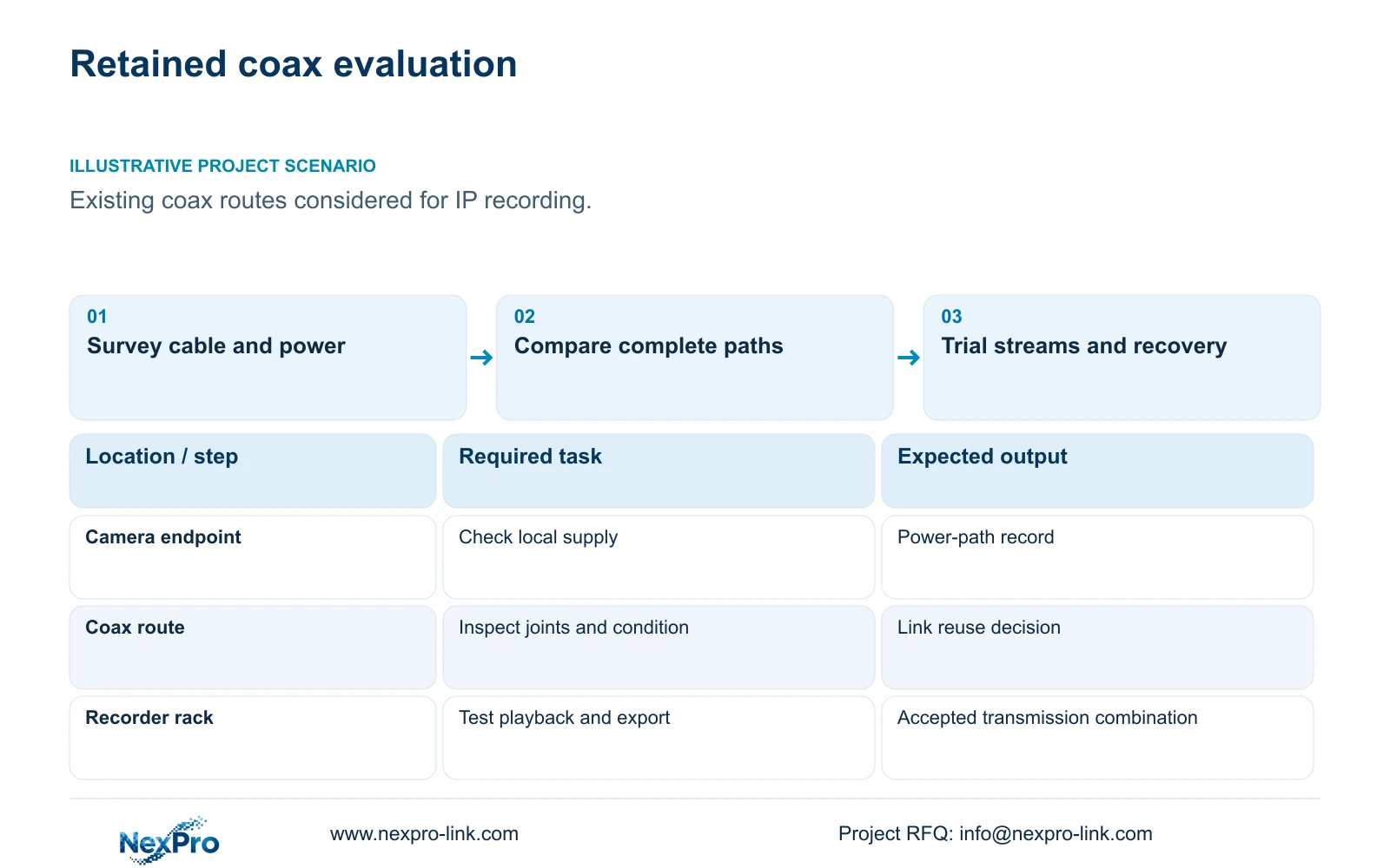
For an analog-to-IP factory retrofit, retain existing coax only where a model-specific transmission arrangement meets the required streams, power and maintenance tasks. Survey actual cable condition and routes before comparing converters with new cabling. An existing analog picture does not establish that the same cable will support the proposed IP workflow.
Illustrative project scenario: A plant has usable coax routes but wants new IP recording and remote management. Assume some routes are difficult to access during production and the team is evaluating converter-based reuse alongside new copper or fibre paths. No converter model, supported distance or site test result is supplied, so reuse remains a conditional option.
Inventory each cable's endpoints, route, joints, connectors, approximate length and accessible repair points. Map the camera supply separately, including any retained local power unit. The project manager should obtain permitted access windows and identify whether changing a shared route affects operating bays. This survey produces a link-specific decision list rather than a blanket instruction to keep or replace all cable.
Section 02
Compare converter reuse with a properly routed replacement
A converter proposal must identify the exact devices at both ends, their supported cable arrangement, bandwidth and power method. Ask whether the camera is locally powered or supplied through the proposed transmission equipment, and include every required supply. Check installation environment and service access for the added devices. None of these capabilities can be inferred from a generic Ethernet-over-coax description.
A recabling proposal should specify the routed permanent links, termination method, patch cords and cabinet positions. Where the required route exceeds the intended copper-link design, evaluate a relocated access cabinet or an appropriate alternative path. Fibre introduces endpoint and local-power requirements of its own; it should be priced as a working path rather than a cable-only substitution.
Compare installed cost at the same accepted recording task. Include cable repair, connectors, converters, power supplies, testing, cabinet changes and future replacement access. A converter can avoid difficult pulling work yet add maintained equipment. New cabling can simplify the transmission arrangement while requiring more production access. Actual quotations and trial results determine the preferred links.
Section 03
Test streams and restart behavior before volume release
Select a representative proposed reuse link and test the complete camera-to-recorder chain. Use the intended resolution, frame rate and recording settings, then perform live viewing, playback and export. Include audio or events only where they are required and supported. Record exact device and firmware identities so the accepted trial can be reproduced in the volume package.
For ordinary-area selection, NexPro-BL2812M55-5MP-DIC-AI lists 2880×1620 output, 25fps@5MP and a 2.8–12mm motorized lens. Its specification does not supply peak watts or a specific ONVIF Profile. Obtain actual power inputs for the transmission design, and verify device/client profile applicability where ONVIF forms part of the intended connection.
Under authorized conditions, test loss and restoration of the relevant power and link. Check whether recording resumes, channel identity remains correct and operator access recovers as intended. Measure or observe recovery for the trial rather than inventing a universal restart time. Retain the previous working arrangement until the owner accepts the migrated link.
Section 04
Use routed lengths to expose individual link problems
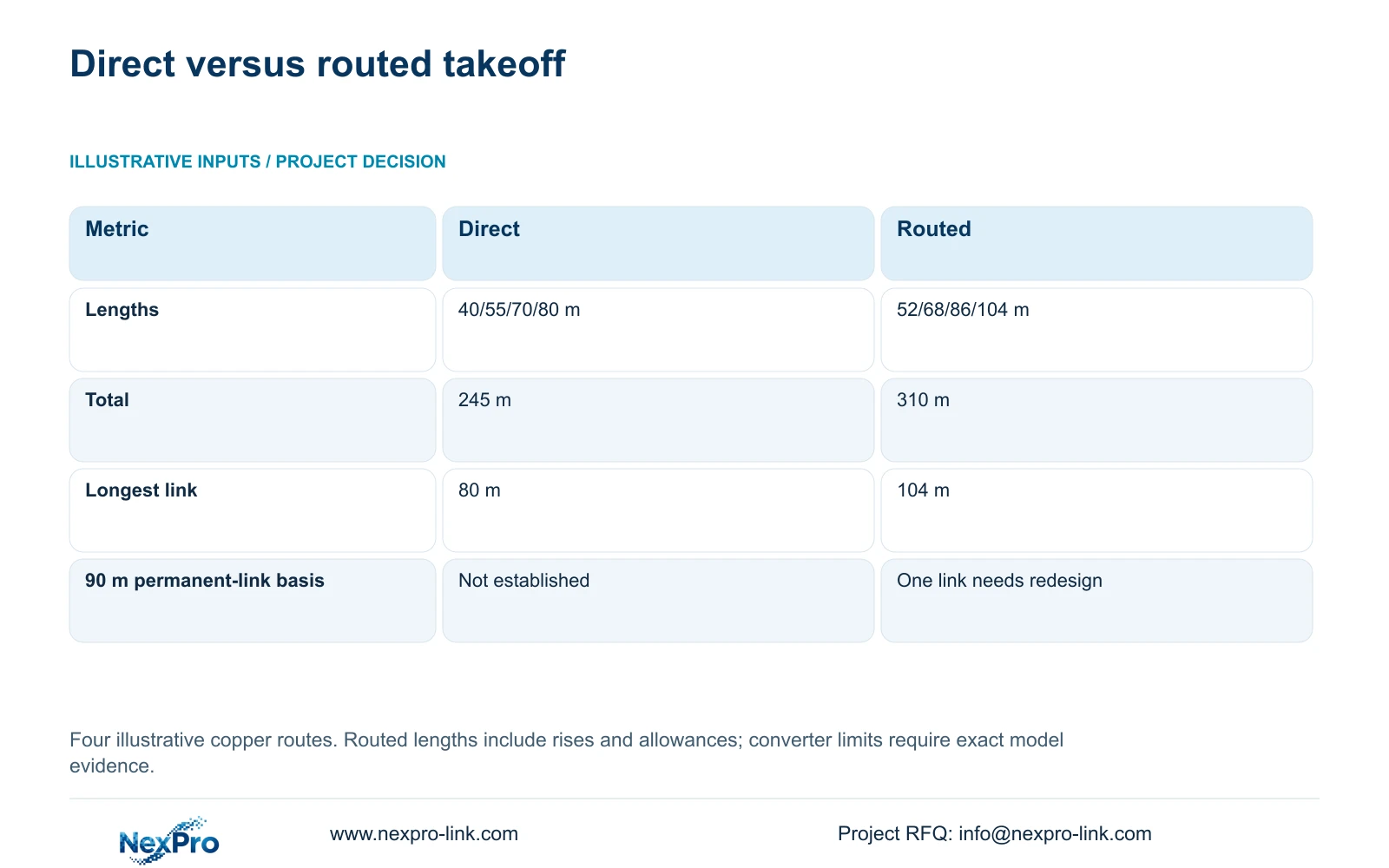
The illustrative four-link takeoff compares straight-line estimates of 40, 55, 70 and 80 m with tray routes, vertical rises and installation allowances of 52, 68, 86 and 104 m. Total length equals the sum of individual links: 40 + 55 + 70 + 80 = 245 m, while 52 + 68 + 86 + 104 = 310 m.
The routed requirement is 65 m higher, and the longest planned permanent link is 104 m rather than 80 m. Fluke guidance distinguishes a typical 90 m copper permanent link from a 100 m complete channel. The 104 m planned permanent link therefore needs redesign under that conventional basis. Direct distance never established its compliance, even though every straight-line estimate appeared shorter.
Check each link before converting total meters into reel quantities. Moving a cabinet or selecting another transmission path changes the takeoff and the interface scope. The 90/100 m distinction does not establish any coax converter's distance capability. That remains specific to the selected technology, cable conditions and complete supported arrangement.
| Link or decision | Direct estimate | Routed takeoff |
|---|---|---|
| Link 1 | 40 m | 52 m |
| Link 2 | 55 m | 68 m |
| Link 3 | 70 m | 86 m |
| Link 4 | 80 m | 104 m, redesign required |
| Total | 245 m | 310 m |
Section 05
Choose reuse link by link and retain a recabling fallback
Prefer converter-based reuse only for links whose cable condition, tested stream path, power and maintainability are acceptable. Use recabling or a redesigned path where the trial fails, repairs are inaccessible or the added converter dependency does not fit the owner’s operation. A mixed migration can be sensible if its interfaces remain documented.
CASE09 demonstrates how retained-link approval changes procurement. With 20 old links approved for retention, its 12 new links total 742 m and use a feasible three-reel cutting plan. Its full 32-link replacement baseline is 1,872 m and seven reels. These are separate illustrative quantities and cannot be combined with the four-link 310 m example.
NexPro-Link's structured-cabling references include the SP5648 Cat6 48-port patch panel and DT968MX tool-less module. They are termination references, not bulk cable or coax converters. Define cable construction and the required link-testing method separately. A complete channel's performance depends on compatible components and installation, not a patch-panel label alone.
Section 06
Release equipment against accepted transmission arrangements
The equipment schedule should identify retained coax, new links, selected transmission devices and local power by link ID. Assign the installer responsibility for route verification and physical tests, the equipment supplier responsibility for exact supplied models, and the owner responsibility for accepted recording tasks. Any unresolved converter input should remain a visible qualification in the quotation.
NexPro-Link can discuss camera and recorder matching, BOQ coordination and relevant technical documents. Where a converter remains unselected, request its functional scope without creating a fictional SKU or capability. Phase-labelled packing can support a controlled migration, but supply coordination does not imply universal mixed-brand compatibility.
Keep the old path available through the agreed cutover checks and record a restore point for failed migration. Local authorization and safe access determine when work can occur. Once each link is accepted, update route, endpoint, power and recovery records before proceeding to the next batch. The final handover should explain the mixed architecture to the team that will maintain it.
Section 07
Buyer questions
Does an old coax image prove the cable is reusable for IP? No. It establishes only that the existing analog arrangement currently produces that image. Evaluate the exact proposed transmission equipment on the actual link at the required stream and power conditions.
Can a Cat6 module solve the 104 m route? No. A termination component does not change the conventional link-length boundary. Redesign the cabinet position or specify another supported path, then revise quantities and testing.
Must every converted link use the same architecture? No, provided the project can maintain the resulting mix. Document each link's transmission method, power source, endpoint devices and recovery checks so service staff do not assume identical behavior.
Section 08
Evaluate your retained cable paths
Send the coax and power inventory, routed link lengths, intended camera stream settings and permitted cutover windows to info@nexpro-link.com to discuss link-specific reuse and recabling requirements.
Engineering references
These sources support the general planning principles. Always use the selected product's current datasheet and applicable project standards for final design.