Reference design · NPL-SCH-016-R1

School campus · 16-zone multichannel Ethernet

Four building groups with passive intermediate distribution and 16 dedicated 10G terminal channels, plus an explicit plan for local terminal power.

H3C equipment · NexPro-Link design, selection & project supply

School networking application environment
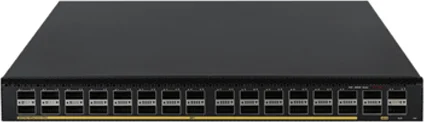
H3C S6550X-32Q-HI — official product photograph
H3C S6550X-32Q-HI · Official product source ↗

H3C multichannel optical Ethernet

A defined starting point for technical review.

This is an illustrative reference design, not a completed installation or a final site quotation. Quantities and capacities follow the assumptions below.

Scale & assumptions

  • Four teaching/library buildings, four sample zones per building. This 16-zone example is not a complete campus or dormitory schedule.
  • Each ES4200 zone serves three computers, one AP, two cameras and one phone, with one spare copper port.
  • Longest reference optical path 800m, with locally maintained AC at all 16 zones. Exact passive assembly mapping, module generations and optical loss require H3C confirmation.
  • Single S6550 core and one gateway path. Dedicated optical channels do not eliminate core, feeder or power failure risks.

Why this architecture

S6550X-32Q-HI supports the documented 40G center optics and four-wavelength terminal sets. Four center groups serve 16 independent 10G Ethernet channels through matched passive distribution; there is no OLT/ONU PON scheduling in this design.

When to choose another approach

Ordinary point-to-point Ethernet offers familiar module pairs and direct troubleshooting where fiber count and intermediate rooms are available. PON may suit dormitory rooms if shared bandwidth and ONU provisioning fit the service plan; compare its optical/power budget separately.

Compare the three architecture families →

Teaching rooms / laboratories

48 sample computer connections and teacher/voice access.

Service boundary: Staff/student/lab policies and authentication; no automatic bandwidth reservation from a port label.

Library / common spaces

16 sample indoor APs across all zones.

Service boundary: Actual concurrency, channel reuse, roaming and exam/event demand determine RF density.

Campus surveillance / administration

32 camera points and 16 phones; recording/management services.

Service boundary: Security VLAN, restricted administration and defined multicast/voice priority.

New construction

Reserve passive distribution locations, accessible terminal enclosures and local power in the architectural plans. Assign each optical wavelength/channel to a terminal ID and retain spare route capacity for expansion.

Upgrade / retrofit

Document existing fibers and attenuation, then demonstrate one matched multichannel group before rollout. Keep live teaching services on the retained Ethernet network until the tested channel, power and policy mappings are accepted.

School campus · 16-zone multichannel Ethernet

Physical connections
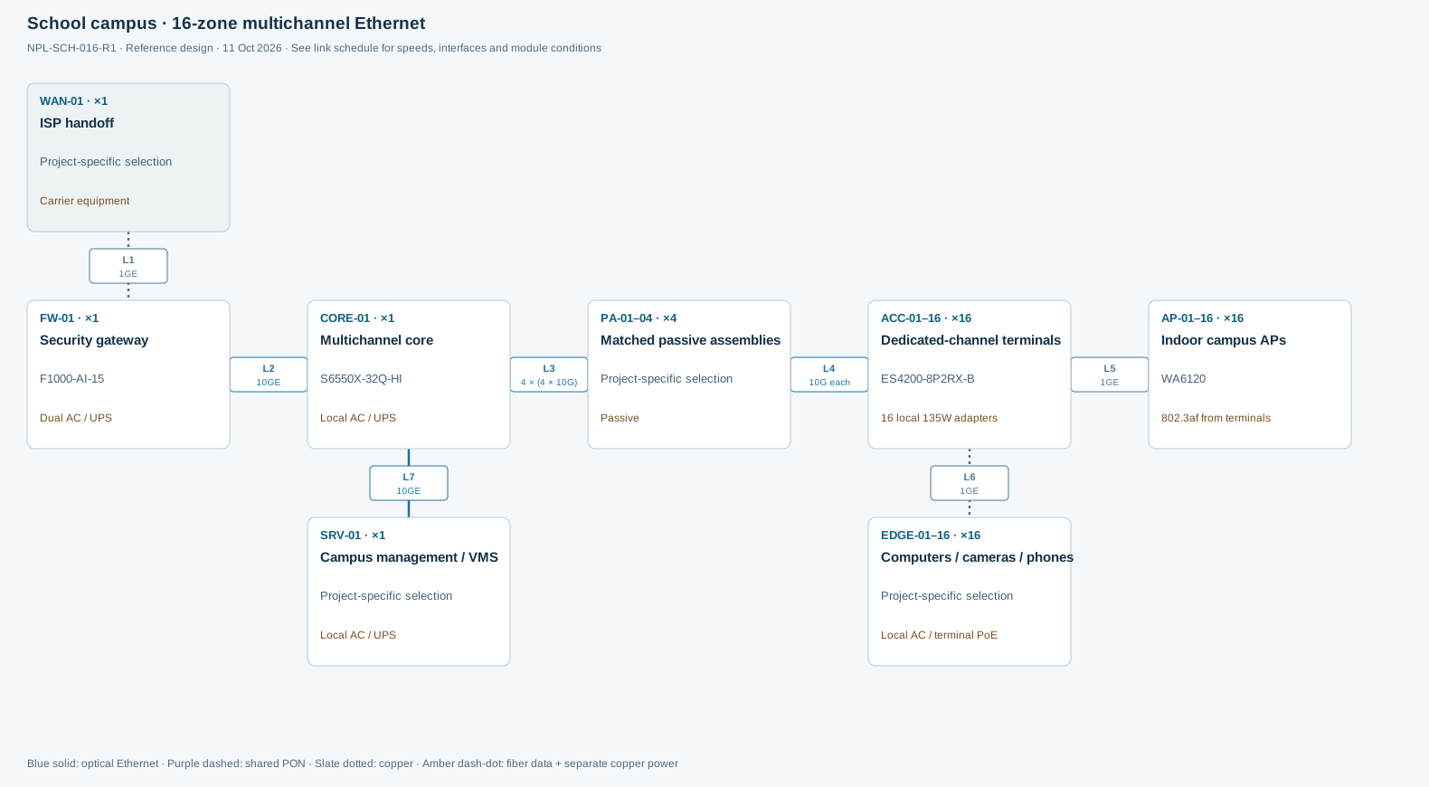
School campus · 16-zone multichannel EthernetReference design. Device IDs match the BOM. Connection IDs match the HTML link schedule. The passive assemblies require no local supply. Each of the 16 active ES4200 terminals has a local adapter and maintained outlet. Central UPS protection alone does not protect those remote outlets. Hybrid remote power is not included here.School campus · 16-zone multichannel EthernetNPL-SCH-016-R1 · Reference design · 11 Oct 2026 · See link schedule for speeds, interfaces and module conditionsL11GEL210GEL34 × (4 × 10G)L410G eachL51GEL61GEL710GEWAN-01 · ×1ISP handoffProject-specific selectionCarrier equipmentFW-01 · ×1Security gatewayF1000-AI-15Dual AC / UPSCORE-01 · ×1Multichannel coreS6550X-32Q-HILocal AC / UPSPA-01–04 · ×4Matched passive assembliesProject-specific selectionPassiveACC-01–16 · ×16Dedicated-channel terminalsES4200-8P2RX-B16 local 135W adaptersAP-01–16 · ×16Indoor campus APsWA6120802.3af from terminalsEDGE-01–16 · ×16Computers / cameras / phonesProject-specific selectionLocal AC / terminal PoESRV-01 · ×1Campus management / VMSProject-specific selectionLocal AC / UPSBlue solid: optical Ethernet · Purple dashed: shared PON · Slate dotted: copper · Amber dash-dot: fiber data + separate copper power
Reference design · NPL-SCH-016-R1 · Device IDs match the BOM. Link IDs match the connection schedule below. Scroll horizontally or open the SVG for a larger view.

Logical services & boundaries

Staff, student, guest, voice, CCTV and management services need authentication, ACLs, routing and QoS. A terminal's dedicated 10G optical channel is separate from the capacity of its GE endpoint ports and the campus WAN.

Electrical power path

The passive assemblies require no local supply. Each of the 16 active ES4200 terminals has a local adapter and maintained outlet. Central UPS protection alone does not protect those remote outlets. Hybrid remote power is not included here.

Link schedule — interfaces, bandwidth and components
Link / endpointsSpeed / sharingPhysical path & interfacesModules / configuration conditions
L1
WAN-01 → FW-01
1GE
Dedicated link / channels
Reference 1GE ISP handoff. Actual contracted bandwidth may be lower.Carrier CPE and copper patch lead; change optics/ports if the actual handoff differs.
L2
FW-01 → CORE-01
10GE
Dedicated link / channels
One branch of a separate supported QSFP+ → 4 × SFP+ breakout group, not one of the four optical access center groups.Candidate LSWM1QSTK3 1m breakout DAC or approved optical equivalent. Confirm gateway/cable compatibility and disable unused branches.
L3
CORE-01 → PA-01–04
4 × (4 × 10G)
Dedicated link / channels
Four single-mode/single-fiber center groups; each supplies four distinct 10G Ethernet channels.4 QSFP-40G-LR4-C-V2 center optics with 4 matching SFP-PLUS-M4-A-V2 terminal sets. Confirm device/release support and passive port map.
L4
PA-01–04 → ACC-01–16
10G each
Dedicated link / channels
16 individually mapped wavelength drops. The matched passive assembly is not a generic PON splitter.16 terminal SFP+ optics from the four sets; do not duplicate their count in BOM. Fiber loss plus connector/passive loss and margin must pass.
L5
ACC-01–16 → AP-01–16
1GE
Dedicated link / channels
One AP per terminal; dedicated copper GE link with af power.16 Cat6 channels, country-code and controller/cloud configuration.
L6
ACC-01–16 → EDGE-01–16
1GE
Dedicated link / channels
6 endpoint links per terminal, 96 channels total.Copper endpoints and class-based PoE check.
L7
CORE-01 → SRV-01
10GE
Dedicated link / channels
Second branch of the separate service breakout group, where supported.Service NIC/DAC compatibility must be confirmed; allocate a separate approved interface if it cannot share this breakout cable.

Declared inputs · reviewable calculations

Capacity and power, with their limits visible.

Planning allocations are assumptions, not measurements of unselected endpoints. Reconcile them with the final device classes, configuration and site tests.

Channel assignment

4 center ports × 4 channels =16 dedicated 10G terminal links.

Supply a port-to-wavelength-to-terminal schedule. This is not 16 ONUs sharing one PON port; exact assembly and software pairing remain an order-release check.

Endpoint capacity

16 × 8 =128 GE ports. 16 × 7 =112 assigned; 16 spare.

Each terminal has up to 8Gb/s nominal endpoint line rate onto a 10G uplink. Core/services/WAN remain separate aggregate bottlenecks.

Terminal power

1 AP at 16W + 2 cameras at 15W + 1 phone at 8W =54W per zone; with 20% reserve =64.8W.

Within the 115W local-adapter limit, above the 40W ES4200 remote-input limit. Keep the local adapters in this BOM.

Failure scope

One core and four feeder/passive groups serve the 16 zones.

A core or feeder failure can affect multiple zones despite dedicated channels. Add separately costed diverse links/devices only after defining recovery requirements.

NPL-SCH-016-R1 · preliminary purchasing basis

The same device IDs. A complete BOM scope.

Download BOM · CSV

Quantities below follow the stated reference assumptions. “To confirm” identifies configuration or survey work still needed before a firm equipment order. Optional resilience is separate from the baseline.

ID / roleModel / itemQty / scopePower / configuration / open items
FW-01
Security gateway
F1000-AI-15
Official source ↗
1 units / sets
Required
Dual AC / UPS
Candidate only: size enabled security services, VPN and sessions before approval.
CORE-01
Multichannel core
S6550X-32Q-HI
Official source ↗
1 units / sets
Required
Local AC / UPS
4 QSFP+ center groups for access, plus a separate configured breakout group for reference 10GE service links.
PA-01–04
Matched passive assemblies
ACCESS-SPLITTER-16LC/LC
Official source ↗
4 units / sets
Required
Passive
ACCESS-SPLITTER-16LC/LC candidates; use one four-channel group per building. Final module generation / mapping to confirm.
ACC-01–16
Dedicated-channel terminals
ES4200-8P2RX-B
Official source ↗
16 units / sets
Required
16 local 135W adapters
10G optical uplink per terminal; 8 GE endpoint ports. Local adapter output budget 115W.
AP-01–16
Indoor campus APs
WA6120
Official source ↗
16 units / sets
Required
802.3af from terminals
One GE AP connection per zone; coverage and busy-hour clients require RF design.
EDGE-01–16
Computers / cameras / phones
Project-specific selection16 units / sets
Required
Local AC / terminal PoE
Per set: 3 computers, 2 cameras and 1 phone; six GE connections.
SRV-01
Campus management / VMS
Project-specific selection1 units / sets
Required
Local AC / UPS
Application/storage scope and NICs to confirm; uses a separate approved service channel.
A-PWR
Core/gateway power configuration, cords and fan sets
Core/gateway power configuration, cords and fan sets1 engineered set
Required
Per approved configuration
Select compatible supplies and airflow for the listed devices. Confirm mains, plugs, loading and service availability; no unlisted PSU is assumed included.
A-LIC
Management, security and WLAN licenses / support
Management, security and WLAN licenses / support1 scope
Required
Per approved configuration
Quote controller or cloud mode, AP capacity, security subscriptions, country codes and support term explicitly. Final SKUs remain subject to configuration review.
A-RACK
Racks, PDU, UPS, earthing and patch management
Racks, PDU, UPS, earthing and patch managementTo confirm surveyed scope
Required
Per approved configuration
Size actual equipment depth, ventilation, total input load, autonomy, outlets and grounding. UPS kVA and battery runtime are not inferred from floor count.
A-HA
Redundant core / gateway and diverse routes
Redundant core / gateway and diverse routesTo confirm option
Optional
Per approved configuration
Add devices, interconnect ports, independent paths and licenses after agreeing the failure scenario and recovery target. Not included in the single-path baseline.
A-CENTER
QSFP-40G-LR4-C-V2 center optics
Official source ↗
4 optics
Required
Per approved configuration
Use matched V2 terminal sets and supported passive components; final platform/release/channel map confirmation required.
A-TERMINAL
SFP-PLUS-M4-A-V2 four-wavelength terminal sets
Official source ↗
4 sets / 16 optics
Required
Per approved configuration
One set per center group. Keep each wavelength tied to the approved passive output / terminal ID.
A-PASSIVE-TRAY
Passive assembly mounting / TRAY-4C configuration
Passive assembly mounting / TRAY-4C configurationTo confirm site set
Required
Per approved configuration
Confirm whether selected assemblies are rack/wall mounted and the actual tray count; do not treat a generic PON tray/splitter as equivalent.
A-LOCAL-PWR
LSAM1POE135W terminal adapters
Official source ↗
16 adapters
Required
Per approved configuration
Local protected AC at each zone.
A-BREAKOUT
LSWM1QSTK3 service breakout DAC candidate
Official source ↗
1 cable
Required
Per approved configuration
1m QSFP+ to four 10G SFP+ branches. Gateway/NIC interoperability and placement must be confirmed; otherwise quote approved separate service interfaces.
A-ODF
Four feeder groups, 16 terminal drops and patching
Four feeder groups, 16 terminal drops and patching1 surveyed lot
Required
Per approved configuration
Document exact optical class, wavelengths, insertion loss, connector type/polish and maintenance margin.

Shared with the topology and BOM

Review the selected H3C candidates.

Compare specifications & configure quantities →
H3C S6550X-32Q-HI — official product photograph

Core / optical aggregation

S6550X-32Q-HI

Dedicated Ethernet channels for campus aggregation.

Budget the chassis, optics and modules; fiber alone supplies no power.

Model, source & quote selection →
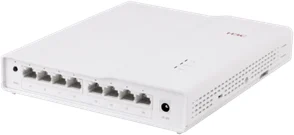
H3C ES4200-8P2RX-B — official product photograph

Room / zone access switch

ES4200-8P2RX-B

Fiber to a work area, with eight copper endpoint ports.

115W with local adapter; 40W with single or dual PoE IN. Do not add the two input budgets together.

Model, source & quote selection →
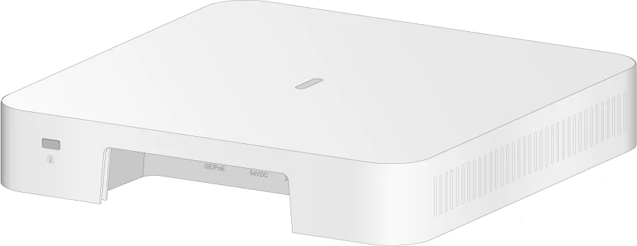
H3C WA6120 — official hardware drawing

Indoor Wi-Fi 6 AP

WA6120

Indoor access with a GE wired connection and low power demand.

Operating consumption ≤12.95W; reserve 15.4W at an af PSE before cable loss assumptions.

Model, source & quote selection →
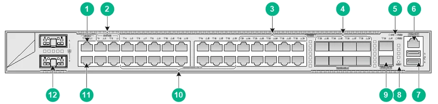
H3C F1000-AI-15 — official hardware drawing

Enterprise security gateway

F1000-AI-15

A candidate WAN / policy boundary, sized after enabled-service throughput review.

Hardware guide lists 48W device power consumption.

Model, source & quote selection →

Next useful inputs

Turn this example into your project.

  • Building/floor plans, classroom and event occupancy
  • Existing fiber types, measured loss, splice/connector counts and routes
  • Authentication platform, country code, client types and teaching applications
  • Local terminal outlets, UPS needs and permitted outage windows
Download the input checklist

NexPro-Link support scope

From selection to coordinated supply.

  • Dedicated channel map with reference device IDs
  • Optics/passive assembly and release compatibility review
  • RF inputs, policy design and power/port calculations
  • Staged campus supply, documentation and acceptance test scope

Detailed deliverables, design fees where applicable, site survey, installation and acceptance responsibilities are agreed for the project stage. Local statutory and specialist system approvals remain with the appointed teams.

Your next step

Start with the information you have.

Send a short requirement, drawings, an existing BOQ or the exact H3C models you need. We will identify the selection and supply scope.

The page, architecture and reference equipment are included automatically. Your selected quote-list quantities can be edited before sending.

Add project details, if known

One attachment up to 3 MB, or a shared-file link. Unknown engineering fields can be confirmed later.

Send a quick inquiry

A short message is enough to get started.

Contact and inquiry details
I’m interested in
Page details included with your inquiry

Request: Network design from drawings · Reference design: NPL-SCH-016-R1 · Architecture: H3C multichannel optical Ethernet · Reference equipment (subject to review): FW-01: F1000-AI-15 ×1; CORE-01: S6550X-32Q-HI ×1; ACC-01–16: ES4200-8P2RX-B ×16; AP-01–16: WA6120 ×16

Add company details or a file (optional)

PDF, DWG, Excel, CSV, JPG, PNG or Word · up to 3 MB.

We use these details to respond to your inquiry. Privacy policy

Prefer a conversation? WhatsApp us or send an email.

Catalog Chat